Panasonic WVNW474S WVNW474S User Guide - Page 10
INSTALLATION, Installation Plans & Preparations
 |
View all Panasonic WVNW474S manuals
Add to My Manuals
Save this manual to your list of manuals |
Page 10 highlights
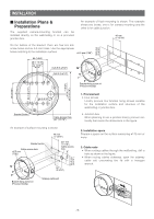
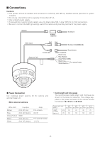
INSTALLATION ■ Installation Plans & Preparations The supplied camera-mounting bracket can be installed directly on the wall/ceiling or on a procured junction box. An example of flush mounting is shown. This example shows two boxes: one is for camera mounting and the other is for cable junction. 46 mm (1-13/16") 83.5 mm (3-5/16") On the bottom of the bracket, there are four 6.5 mm screw holes and six 5.5 mm holes. Use the appropriate holes matching to the installation surface. ø5.5 mm (7/32") 85 (3-3/8") 46 (1-13/16") 4.4 (3/16") 6-φ5.5 (6-φ7/32") 4-φ6.5 (6-φ1/4") 7 (9/32") φ175 (6-7/8") Bracket fixing screw x4 (Procured locally) 85 (3-3/8") 83.5 (3-5/16") 55 (2-3/16") Bracket Center Cable Access Hole φ27 (1-1/16") An example of surface mounting is shown. Bracket center Cable access hole ø5.5 mm (7/32") 46 mm (1-13/16") ø27 mm (1-1/16") Cable access hole 55 (2-3/16") 7 mm (1/4) 83.5 mm (3-5/16") 1. Procurement • Four screws Locally procure four bracket fixing screws suitable for the installation surface and structure of the wall/ceiling or junction box. • Junction box When planning to use a junction box(s), procure one locally that meets the dimensions in the figure. 2. Installation space Prepare a space on the surface measuring ø175 mm or more. 3. Cable route • When routing cables through the wall/ceiling, drill a hole as shown in the figure. • When routing cables sideways, open the sideway cable exit unscrewing the lid with a hexagon wrench. Bracket fixing screw x4 (Procured locally) Sideway cable exit -10-
-
 1
1 -
2
-
3
-
4
-
 5
5 -
 6
6 -
 7
7 -
 8
8 -
 9
9 -
 10
10 -
 11
11 -
 12
12 -
 13
13 -
 14
14 -
 15
15 -
16
-
17
-
18
-
19
-
20
-
21
-
22
-
23
-
24
-
25
-
26
-
27
-
28
-
29
-
30
-
31
-
32
-
33
-
34
-
35
-
36
-
37
-
38
-
39
-
40
-
41
-
42
-
43
-
44
-
45
-
46
-
47
-
48
-
49
-
50
-
51
-
52
-
53
-
54
-
55
-
56
-
57
-
58
-
59
-
60
-
61
-
62
-
63
-
64
-
65
-
66
-
67
-
68
 |
 |
