Panasonic WVNW474S WVNW474S User Guide - Page 13
Image Adjustment, Video Output Connection, Control Connector, Network Port Connection
 |
View all Panasonic WVNW474S manuals
Add to My Manuals
Save this manual to your list of manuals |
Page 13 highlights
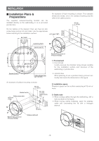
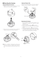
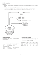
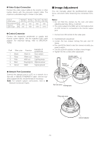
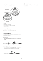
● Video Output Connection Connect the video output cable to the monitor or other system device with the procured coaxial cable. The maximum extensible length is shown in the table. Type of coaxial cable RG-59/U (3C-2V) Recommended (m) 250 maximum cable length (ft) 825 RG-6/U (5C-2V) 500 1650 RG-11/U RG-15/U (7C-2V) (10C-2V) 600 800 1 980 2 640 ● Control Connector Connect the respective peripherals to supply and receive control signals. Use the supplied 5-pin cable adapter. For electrical ratings, refer to SPECIFICATIONS. Pin# Wire color Function Example of peripherals 1 Black Alarm in Door switch 2 Gray Alarm out Buzzer 3 Pink AUX out Lighting lamp 4 Red Day/night in Optical sensor 5 Green GND Signal ground ■ Image Adjustment You can manually adjust the pan/tilt/azimuth angles, focus, and zoom while observing the connected monitor. Notes: • Do not hold the camera by the lens unit when adjusting panning, tilting, or azimuth. • The video output to the BNC will be interrupted while an LCD monitor is connected to the monitor output jack. 1. Connect an LCD monitor to the video jack. 2. Pan/tilt/azimuth adjustment • Loosen the two screws locking the pan and tilt tables. • Pan and tilt the table to aim the camera at what you need to watch. • Turn the azimuth adjuster to obtain a level image. • Tighten the two screws after adjustment. Variable angles plus or minus 75° (max.) Monitor output jack ● Network Port Connection Connect the network port to a PC or a network via a hub with a 10BASE-T/100BASETX cable. Use the supplied adapter (RJ-45, female-female) if necessary. Note: For network system connections, refer to ■ Network Connection Types. Pan lock screw Panning table Tilting lock screw -13- Azimuth adjuster
-
 1
1 -
2
-
3
-
4
-
5
-
6
-
7
-
 8
8 -
 9
9 -
 10
10 -
 11
11 -
 12
12 -
 13
13 -
 14
14 -
 15
15 -
 16
16 -
 17
17 -
 18
18 -
19
-
20
-
21
-
22
-
23
-
24
-
25
-
26
-
27
-
28
-
29
-
30
-
31
-
32
-
33
-
34
-
35
-
36
-
37
-
38
-
39
-
40
-
41
-
42
-
43
-
44
-
45
-
46
-
47
-
48
-
49
-
50
-
51
-
52
-
53
-
54
-
55
-
56
-
57
-
58
-
59
-
60
-
61
-
62
-
63
-
64
-
65
-
66
-
67
-
68
 |
 |
