Panasonic WVSC385 WVSC385 User Guide - Page 16
Wire through a hole in the ceiling, Step 1 - parts
 |
View all Panasonic WVSC385 manuals
Add to My Manuals
Save this manual to your list of manuals |
Page 16 highlights
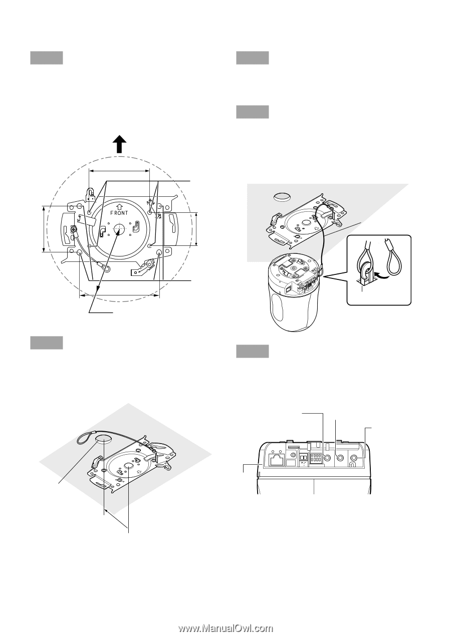
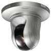
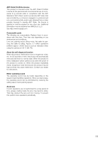
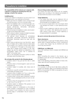
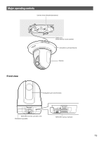
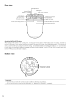
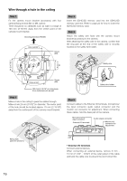
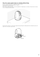
Wire through a hole in the ceiling Step 1 Fix the camera mount bracket (accessory) with four optional fixing screws (M4 or M6, option). There should be no obstacles such as wall in a range of 100 mm {3-15/16"} away from the center point of the camera mount bracket. Shooting direction (FRONT) 83.5 {3-9/32"} Screw (M4) Step 3 Insert the SDHC/SD memory card into the SDHC/SD memory card slot. Refer to page 24 for how to insert the SDHC/SD memory card. Step 4 Attach the safety wire fixed with the camera mount bracket (accessory) to the camera. After attaching the safety wire to the camera, confirm that the ring part at the end of the safety wire is securely hooked on the safety wire holder. Safety wire 64 {2-17/32"} OPEN LOCK FRONT OPEN LOCK FRONT 46 {1-13/16"} 110 {4-5/16"} Screw (M6) 100 mm {3-15/16"} or more away from obstacles such as wall Step 2 Make a hole in the ceiling to pass the cables through. Make a hole 25 mm {31/32"} in diameter. The center point of the hole should be located approx. 75 mm {2-15/16"} away from the center point of the camera mount bracket. Wiring hole (ø25 mm {31/32"}) {2-7155/m16m"} Safety wire holder Step 5 Connect cables to the External I/O terminals, microphone/ line input connector, audio output connector and the monitor out connector for adjustment. When connecting these cables, hold the base part of the camera. Microphone/line input connector Audio output connector External I/O terminals 10BASE-T/ 100BASE-TX LINK ACT INITIAL SET POWER EXT I/O MIC/LINE IN AUDIO OUT MONITOR OUT Monitor out connector for adjustment 12V IN 4 3 2 1 Base part • External I/O terminals Connect external devices. When connecting an external device, remove 9 mm 10 mm {11/32" - 13/32"} of the outer jacket of the cable and twist the cable core to prevent the short circuit first. 16
-
 1
1 -
2
-
3
-
4
-
5
-
6
-
7
-
8
-
9
-
10
-
 11
11 -
 12
12 -
 13
13 -
 14
14 -
 15
15 -
 16
16 -
 17
17 -
 18
18 -
 19
19 -
 20
20 -
 21
21 -
22
-
23
-
24
-
25
-
26
-
27
-
28
-
29
-
30
-
31
-
32
-
33
-
34
-
35
-
36
 |
 |