Panasonic WVSC385 WVSC385 User Guide - Page 18
Important, Step 7, Recommended tightening torque, network connector. - poe
 |
View all Panasonic WVSC385 manuals
Add to My Manuals
Save this manual to your list of manuals |
Page 18 highlights
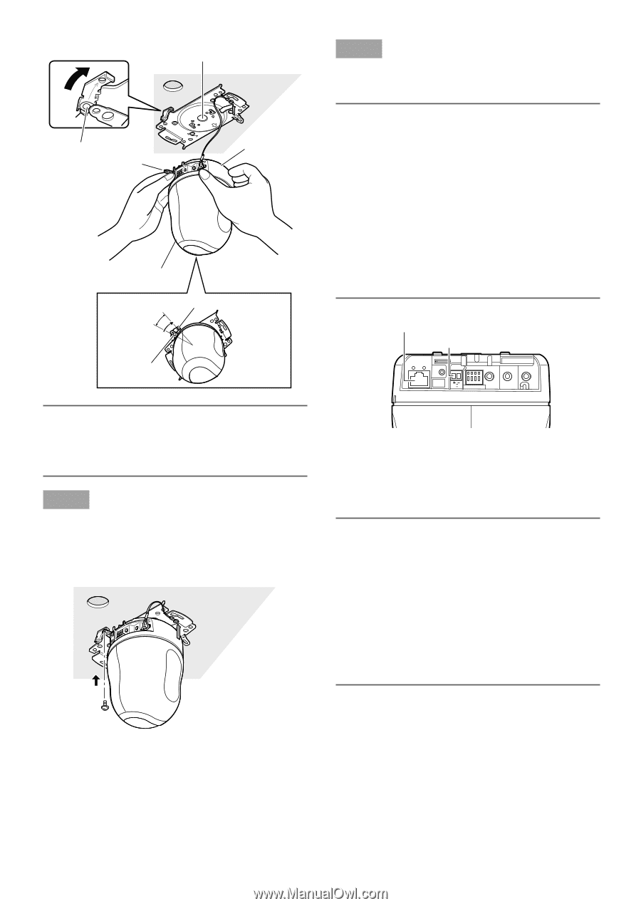
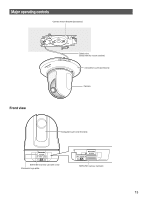
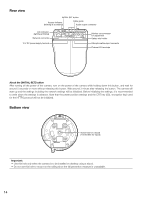
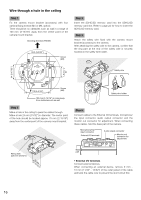
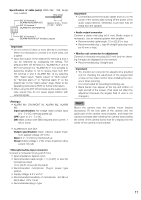
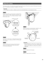
Center of the camera mount bracket OPEN LOCK FRONT Guide part Lock plate Base part Rotate 20 ° Moving part Camera mount bracket (accessory) Camera Important: • When mounting the camera onto the camera mount bracket, hold the base part of the camera. Mounting the camera while holding the moving part may result in malfunction. Step 7 Fix the camera on the camera mount bracket (accessory) using the camera fixing screw (accessory). Recommended tightening torque: 0.68 N·m {0.50 lbf·ft} Fixing screw (accessory) Step 8 Connect the cables to the network connector and the power inlet. Important: • When the power of the camera is turned on, the cam- era will start panning and the position will automatically be initialized. • Do not touch the camera in the process of initialization. Otherwise, it may fail to initialize and may cause malfunction. • When the camera has been inadvertently touched and moved after the initialization is complete, the preset positions may be inaccurate. In this case, use the position refresh function or restart the camera to correct the preset positions. Refer to the Operating Instructions (PDF) for further information. Network connector 12 V DC power supply terminal 10BASE-T/ 100BASE-TX LINK ACT INITIAL SET POWER EXT I/O MIC/LINE IN AUDIO OUT MONITOR OUT 12V IN 4 3 2 1 • Network connector Connect a LAN cable (category 5 or better, STP*) to the network connector. * PAL model only Important: • Use all 4 pairs (8 pins) of the LAN cable. • The maximum cable length is 100 m {328'}. • Make sure that the PoE device in use is compliant with IEEE802.3af standard. • When connecting both the 12 V DC power supply and the PoE device for power supply, 12 V DC will be used for power supply. • When the LAN cable is disconnected once, reconnect the cable after about 2 seconds. When the cable is quickly reconnected, the power may not be supplied from the PoE device. 18
-
 1
1 -
2
-
3
-
4
-
5
-
6
-
7
-
8
-
9
-
10
-
11
-
12
-
 13
13 -
 14
14 -
 15
15 -
 16
16 -
 17
17 -
 18
18 -
 19
19 -
 20
20 -
 21
21 -
 22
22 -
 23
23 -
24
-
25
-
26
-
27
-
28
-
29
-
30
-
31
-
32
-
33
-
34
-
35
-
36
 |
 |