Panasonic WVSC385 WVSC385 User Guide - Page 17
EXT I/O terminal 3 is ALARM IN 3. It is possible to, Open or 4 V - 5 V DC - instructions
 |
View all Panasonic WVSC385 manuals
Add to My Manuals
Save this manual to your list of manuals |
Page 17 highlights
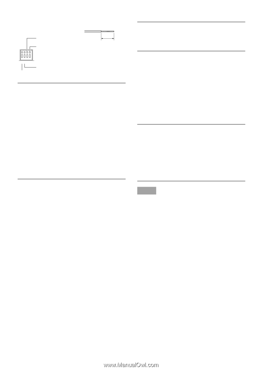
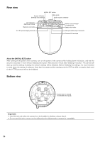
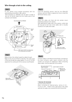
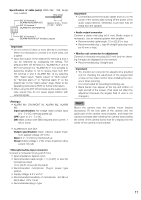
Specification of cable (wire): AWG #22 - #28, Single core, twisted Strip range EXT I/O terminal 2 (ALARM IN2/ALARM OUT) EXT I/O terminal 1 (ALARM IN1/ DAY/NIGHT IN) Approx. 9 mm - 10 mm {11/32" - 13/32"} 4 3 2 1 GND EXT I/O terminal 3 (ALARM IN3/AUX OUT (Auxiliary output)) Important: • Do not connect 2 wires or more directly to a terminal. When it is necessary to connect 2 or more wires, use a splitter. • Input and output of the external I/O terminal 2 and 3 can be switched by configuring the setting. The default of EXT I/O terminal 2 is "ALARM IN 2" and of EXT I/O terminal 3 is "ALARM IN 3". It is possible to determine whether or not to receive input from EXT I/O terminal 2 and 3 (ALARM IN2, 3) by selecting "Off", "Alarm input", "Alarm output" or "AUX output" for "Terminal alarm 2" or "Terminal alarm 3" on the [Alarm] tab on the "Alarm setup" page. Refer to the Operating Instructions (PDF) for further information. • When using the EXT I/O terminals as the output terminals, ensure they do not cause signal collision with external signals. • ALARM IN1/ DAY/NIGHT IN, ALARM IN2, ALARM IN3 Input specification: No-voltage make contact input (4 V - 5 V DC, internally pulled up) OFF: Open or 4 V - 5 V DC ON: Make contact with GND (required drive current: 1 mA or more) • ALARM OUT, AUX OUT Output specification: Open collector output (maximum applied voltage: 20 V DC) Open: 4 V - 5 V DC by internal pull-up Close: Output voltage 1 V DC or less (maximum drive current: 50 mA) • Microphone/line input connector Connect a monaural mini plug (ø3.5 mm). • Input impedance: Approx. 2 kΩ • Recommended cable length: 1 m {3.28'} or less (for microphone input) 10 m {32.8'} or less (for line input) • Recommended microphone: Plug-in power type (option) • Supply voltage: 2.5 V ±0.5 V • Recommended sensitivity of microphone: -48 dB ±3 dB (0 dB=1 V/Pa,1 kHz) • Recommended plug: L type Important: • Connect/disconnect the audio cables and turn on the power of the camera after turning off the power of the audio output devices. Otherwise, loud noise may be heard from the speaker. • Audio output connector Connect a stereo mini plug (ø3.5 mm) (Audio output is monaural.). Use an external speaker with amplifier. • Recommended cable length: 10 m {32.8'} or less • Recommended plug: L type (A straight type plug must be 40 mm or less.) • Monitor out connector for adjustment Connect a monaural mini plug (ø3.5 mm) (only for checking if images are displayed on the monitor). • Recommended plug: Straight type Important: • The monitor out connector for adjustment is provided only for checking the adjustment of the angular field of view on the video monitor when installing the camera or when servicing. It is not provided for recording/monitoring use. • Black bands may appear at the top and bottom or right and left of the screen. (That does not affect the adjustment because the angular field of view is not changed.) Step 6 Mount the camera onto the camera mount bracket (accessory). Fit the lock plate of the camera onto the guide part of the camera mount bracket, and rotate the camera clockwise after inserting the camera while putting the center of the camera (screw hole for a tripod) onto the center of the camera mount bracket. 17
-
 1
1 -
2
-
3
-
4
-
5
-
6
-
7
-
8
-
9
-
10
-
11
-
 12
12 -
 13
13 -
 14
14 -
 15
15 -
 16
16 -
 17
17 -
 18
18 -
 19
19 -
 20
20 -
 21
21 -
 22
22 -
23
-
24
-
25
-
26
-
27
-
28
-
29
-
30
-
31
-
32
-
33
-
34
-
35
-
36
 |
 |