Philips 37PF9631D User manual - Page 40
Connect a VCR or DVD recorder
 |
UPC - 609585113794
View all Philips 37PF9631D manuals
Add to My Manuals
Save this manual to your list of manuals |
Page 40 highlights
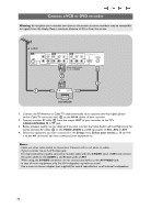
Connect a VCR or DVD recorder Warning: do not place your recorder too close to the screen as some recorders may be susceptible for signals from the display. Keep a minimum distance of 0,5 m from the screen. CABLE AV3 S-VIDEO DIGITAL AV2 L AUDIO OUT Pr Pb Y AV1 For DVI-HDMI convertor cable Pr Pb Y connect AV1 Audio L/R ANTENNA 75 R AUDIO VIDEO AUDIO VIDEO HDMI L R L R VIDEO AV1 / AV2 / AV3 : L + R + VIDEO 3 IN OUT RECORDER 1. Connect the RF Antenna or Cable TV cable (eventually via an optional two-way signal splitter and/or Cable TV converter box) 1 to the RF IN socket of your recorder. 2. Connect another RF cable 2 from the output OUT of your recorder to the TV's CABLE/ANTENNA 75 Ω x jack. 3. Better playback quality can be obtained if you also connect the Video, Audio Left and Right (only for stereo devices) AV cables 3 to the VIDEO, AUDIO L and R input jacks of AV1, AV2 or AV3 4. Select the equipment you have connected in the Setup menu, Select your source, p. 20 and link it to the AV connector you have connected your equipment to. Notes: - cables are often color-coded to connectors. Connect red to red, white to white.... - if your recorder has an S-VHS video jack: For improved picture quality, connect an S-video cable with the S-VIDEO input of AV3 and connect the audio cables to the AUDIO L and R input jacks of AV3. When using the S-VIDEO connector do not connect any device to the AV3 VIDEO jack; - in case of mono equipment, only the left loudspeaker reproduces sound. Use a mono to stereo adapter (not supplied) for sound reproduction via all internal loudspeakers. 38
-
 1
1 -
2
-
3
-
4
-
5
-
6
-
7
-
8
-
9
-
10
-
11
-
12
-
13
-
14
-
15
-
16
-
17
-
18
-
19
-
20
-
21
-
22
-
23
-
24
-
25
-
26
-
27
-
28
-
29
-
30
-
31
-
32
-
33
-
34
-
 35
35 -
 36
36 -
 37
37 -
 38
38 -
 39
39 -
 40
40 -
 41
41 -
 42
42 -
 43
43 -
 44
44 -
 45
45 -
46
-
47
-
48
-
49
-
50
-
51
-
52
-
53
-
54
-
55
-
56
-
57
-
58
-
59
-
60
 |
 |
