Pioneer DEH-4300UB Owners Manual - Page 8
Using an AUX source, Sound muting, Operating this unit, Connections, Installation - wiring
 |
UPC - 884938116497
View all Pioneer DEH-4300UB manuals
Add to My Manuals
Save this manual to your list of manuals |
Page 8 highlights
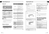
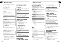
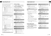
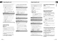
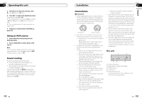
Section 02 Operating this unit 5 Press M.C. to select the primary color. R (red)-G (green)-B (blue) 6 Turn M.C. to adjust the brightness level. Adjustment range: 0 to 60 # You cannot select a level below 10 for all three of R (red), G (green), and B (blue) at the same time. # You can also perform the same operation on other colors. 7 Press M.C. and hold until CUSTOM appears. Using an AUX source 1 Insert the stereo mini plug into the AUX input jack. 2 Press S (SRC/OFF) to select AUX as the source. Note AUX cannot be selected unless the auxiliary setting is turned on. For more details, refer to AUX (auxiliary input) on page 12. Sound muting Sound is muted automatically when: ! A call is made or received using a cell phone connected to this unit. ! Voice guidance is output from a connected Pioneer navigation unit. The sound is turned off, MUTE is displayed and no audio adjustments, except volume control, are possible. Operation returns to normal when the phone connection or the voice guidance is ended. 14 En Installation Section 03 English N STAR Connections Important ! When installing this unit in a vehicle without an ACC (accessory) position on the ignition switch, failure to connect the red cable to the terminal that detects operation of the ignition key may result in battery drain. F O OF T ACC position No ACC position ! Use of this unit in conditions other than the following could result in fire or malfunction. - Vehicles with a 12-volt battery and negative grounding. - Speakers with 50 W (output value) and 4 ohm to 8 ohm (impedance value). ! To prevent a short-circuit, overheating or malfunction, be sure to follow the directions below. - Disconnect the negative terminal of the battery before installation. - Secure the wiring with cable clamps or adhesive tape. Wrap adhesive tape around wiring that comes into contact with metal parts to protect the wiring. - Place all cables away from moving parts, such as the gear shift and seat rails. - Place all cables away from hot places, such as near the heater outlet. - Do not connect the yellow cable to the battery by passing it through the hole to the engine compartment. - Cover any disconnected cable connectors with insulating tape. - Do not shorten any cables. - Never cut the insulation of the power cable of this unit in order to share the power with other devices. The current capacity of the cable is limited. - Use a fuse of the rating prescribed. - Never wire the negative speaker cable directly to ground. - Never band together negative cables of multiple speakers. ! When this unit is on, control signals are sent through the blue/white cable. Connect this cable to the system remote control of an external power amp or the vehicle's auto-antenna relay control terminal (max. 300 mA 12 V DC). If the vehicle is equipped with a glass antenna, connect it to the antenna booster power supply terminal. ! Never connect the blue/white cable to the power terminal of an external power amp. Also, never connect it to the power terminal of the auto antenna. Doing so may result in battery drain or a malfunction. ! The black cable is ground. Ground cables for this unit and other equipment (especially, high-current products such as power amps) must be wired separately. If they are not, an accidental detachment may result in a fire or malfunction. This unit 1 2 34 5 1 Power cord input 2 Rear output or subwoofer output 3 Antenna input 4 Fuse (10 A) 5 Wired remote input Hard-wired remote control adaptor can be connected (sold separately). En 15
-
 1
1 -
2
-
 3
3 -
 4
4 -
 5
5 -
 6
6 -
 7
7 -
 8
8 -
 9
9 -
 10
10 -
 11
11 -
 12
12 -
 13
13 -
14
-
15
-
16
-
17
-
18
-
19
-
20
-
21
-
22
-
23
-
24
-
25
-
26
-
27
-
28
-
29
-
30
-
31
-
32
-
33
-
34
-
35
-
36
-
37
-
38
-
39
-
40
-
41
-
42
-
43
-
44
-
45
-
46
-
47
-
48
-
49
-
50
-
51
-
52
-
53
-
54
-
55
-
56
-
57
-
58
-
59
-
60
-
61
-
62
-
63
-
64
-
65
-
66
-
67
-
68
-
69
-
70
-
71
-
72
-
73
-
74
-
75
-
76
-
77
-
78
-
79
-
80
-
81
-
82
-
83
-
84
-
85
-
86
-
87
-
88
-
89
-
90
-
91
-
92
-
93
-
94
-
95
-
96
-
97
-
98
-
99
-
100
 |
 |