Pioneer DEH-4300UB Owners Manual - Page 9
Installation
 |
UPC - 884938116497
View all Pioneer DEH-4300UB manuals
Add to My Manuals
Save this manual to your list of manuals |
Page 9 highlights
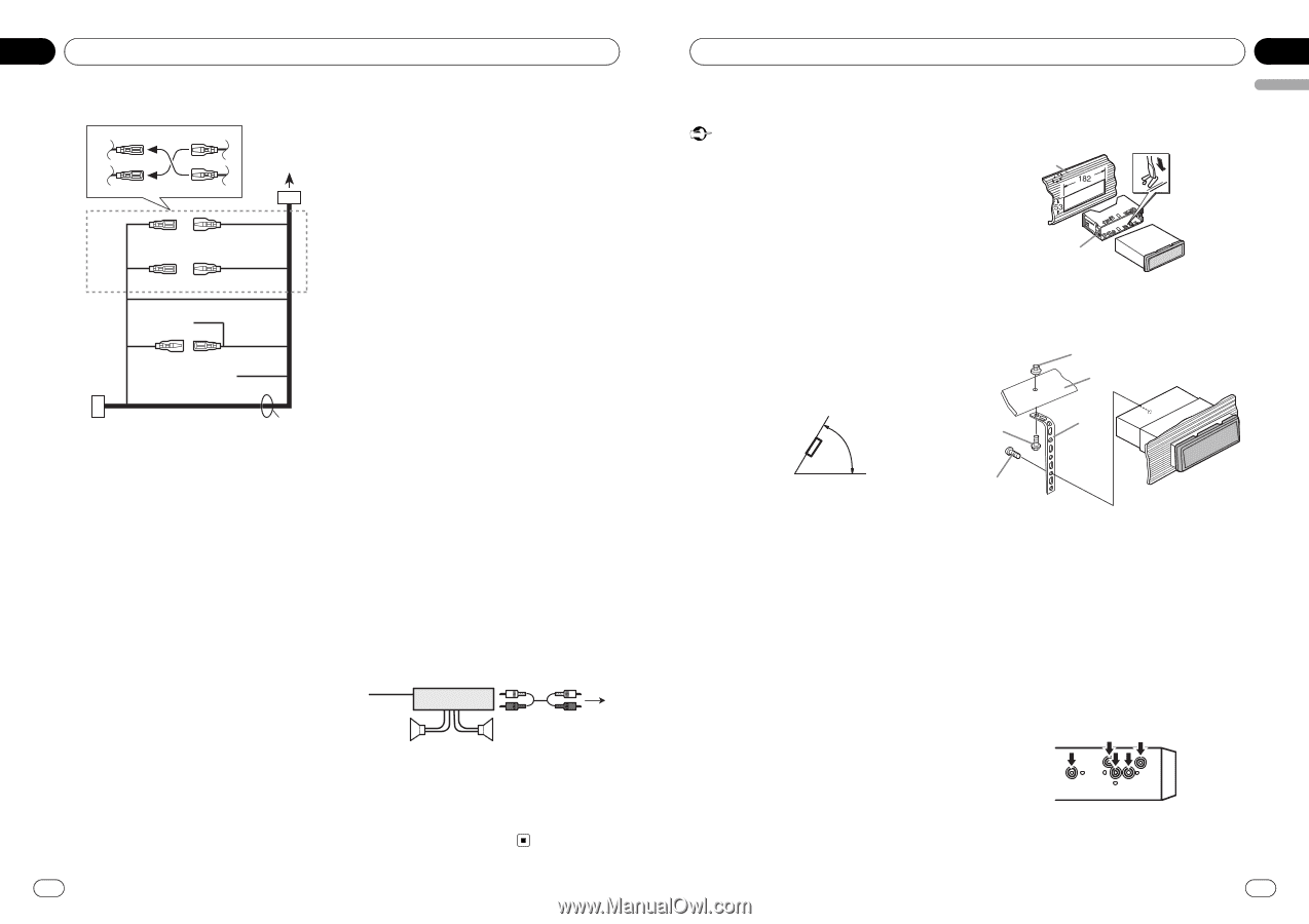
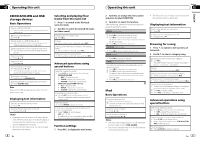
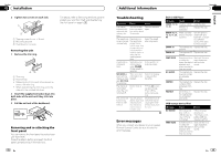
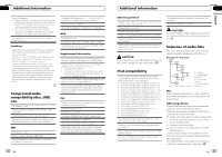
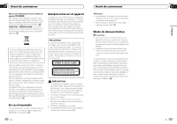
Section 03 Installation Power cord 3 4 25 6 1 34 7 56 8 a 9b c e d 1 To power cord input 2 Depending on the kind of vehicle, the function of 3 and 5 may be different. In this case, be sure to connect 4 to 5 and 6 to 3. 3 Yellow Back-up (or accessory) 4 Yellow Connect to the constant 12 V supply terminal. 5 Red Accessory (or back-up) 6 Red Connect to terminal controlled by ignition switch (12 V DC). 7 Connect leads of the same color to each other. 8 Black (chassis ground) 9 Blue/white The pin position of the ISO connector will differ depending on the type of vehicle. Connect 9 and b when Pin 5 is an antenna control type. In another type of vehicle, never connect 9 and b. a Blue/white Connect to system control terminal of the power amp (max. 300 mA 12 V DC). b Blue/white Connect to auto-antenna relay control terminal (max. 300 mA 12 V DC). c Yellow/black If you use an equipment with Mute function, wire this lead to the Audio Mute lead on that equipment. If not, keep the Audio Mute lead free of any connections. d Speaker leads White: Front left + White/black: Front left * Gray: Front right + Gray/black: Front right * Green: Rear left + or subwoofer + Green/black: Rear left * or subwoofer * Violet: Rear right + or subwoofer + Violet/black: Rear right * or subwoofer * e ISO connector In some vehicles, the ISO connector may be divided into two. In this case, be sure to connect to both connectors. Notes ! Change the initial setting of this unit. Refer to SW CONTROL (rear output and subwoofer setting) on page 12. The subwoofer output of this unit is monaural. ! When using a subwoofer of 70 W (2 Ω), be sure to connect the subwoofer to the violet and violet/black leads of this unit. Do not connect anything to the green and green/black leads. Power amp (sold separately) Perform these connections when using the optional amplifier. 1 3 2 4 5 5 1 System remote control Connect to Blue/white cable. 2 Power amp (sold separately) 3 Connect with RCA cable (sold separately) 4 To Rear output or subwoofer output 5 Rear speaker or subwoofer 16 En Installation Section 03 English Installation Important ! Check all connections and systems before final installation. ! Do not use unauthorized parts as this may cause malfunctions. ! Consult your dealer if installation requires dril- ling of holes or other modifications to the vehicle. ! Do not install this unit where: - it may interfere with operation of the vehi- cle. - it may cause injury to a passenger as a re- sult of a sudden stop. ! The semiconductor laser will be damaged if it overheats. Install this unit away from hot places such as near the heater outlet. ! Optimum performance is obtained when the unit is installed at an angle of less than 60°. 60° 2 Secure the mounting sleeve by using a screwdriver to bend the metal tabs (90°) into place. 1 2 1 Dashboard 2 Mounting sleeve 3 Install the unit as illustrated. 1 2 3 4 DIN front/rear mount This unit can be properly installed using either front-mount or rear-mount installation. Use commercially available parts when installing. DIN Front-mount 1 Insert the mounting sleeve into the dashboard. For installation in shallow spaces, use the supplied mounting sleeve. If there is enough space, use the mounting sleeve that came with the vehicle. 5 1 Nut 2 Firewall or metal support 3 Metal strap 4 Screw 5 Screw (M4 × 8) # Make sure that the unit is installed securely in place. An unstable installation may cause skipping or other malfunctions. DIN Rear-mount 1 Determine the appropriate position where the holes on the bracket and the side of the unit match. En 17
-
 1
1 -
2
-
3
-
 4
4 -
 5
5 -
 6
6 -
 7
7 -
 8
8 -
 9
9 -
 10
10 -
 11
11 -
 12
12 -
 13
13 -
 14
14 -
15
-
16
-
17
-
18
-
19
-
20
-
21
-
22
-
23
-
24
-
25
-
26
-
27
-
28
-
29
-
30
-
31
-
32
-
33
-
34
-
35
-
36
-
37
-
38
-
39
-
40
-
41
-
42
-
43
-
44
-
45
-
46
-
47
-
48
-
49
-
50
-
51
-
52
-
53
-
54
-
55
-
56
-
57
-
58
-
59
-
60
-
61
-
62
-
63
-
64
-
65
-
66
-
67
-
68
-
69
-
70
-
71
-
72
-
73
-
74
-
75
-
76
-
77
-
78
-
79
-
80
-
81
-
82
-
83
-
84
-
85
-
86
-
87
-
88
-
89
-
90
-
91
-
92
-
93
-
94
-
95
-
96
-
97
-
98
-
99
-
100
 |
 |