Pioneer DEH-P8300UB Owner's Manual - Page 22
Installation - remote
 |
UPC - 884938118569
View all Pioneer DEH-P8300UB manuals
Add to My Manuals
Save this manual to your list of manuals |
Page 22 highlights
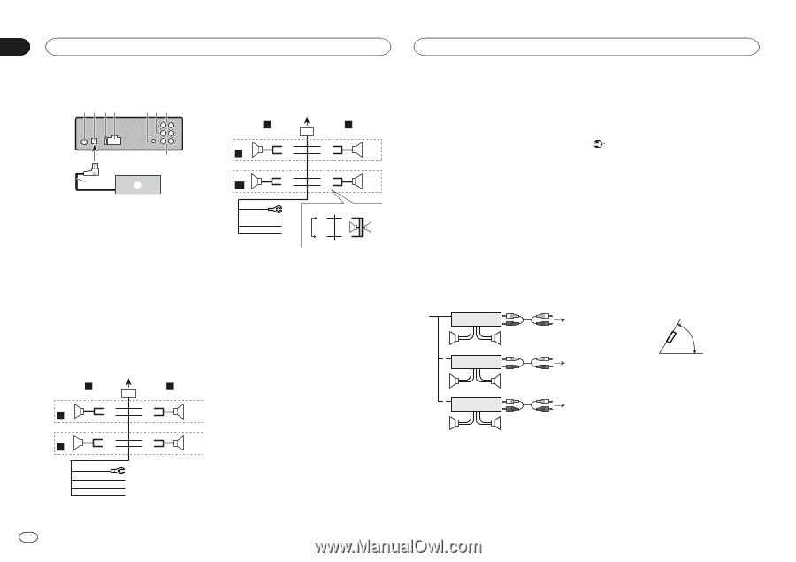
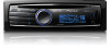
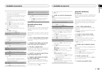
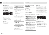
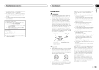
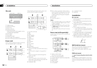
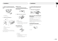
Section 04 Installation Installation This unit 1 2 34 56 7 8 9 a Perform these connections when using a subwoofer without the optional amplifier. L 2 4 6 F 7 i a SW b 1 R 3 8 9 c d 1 Antenna input 2 IP-BUS input (blue) 3 Fuse (10 A) 4 Power cord input 5 Wired remote input Hard-wired remote control adaptor can be connected (sold separately). 6 Front output 7 Rear output 8 Subwoofer output 9 IP-BUS cable (sold separately) a Pioneer IP-BUS accessories (sold separately) Power cord Perform these connections when not connecting a rear speaker lead to a subwoofer. L 1 R 2 3 4 6 8 F 7 9 5 a c R b d e f g h ej f ac gk l h bd 1 To power cord input 2 Left 3 Right 4 Front speaker 5 Rear speaker 6 White 7 White/black 8 Gray 9 Gray/black a Green b Green/black c Violet d Violet/black e Black (chassis ground) Connect to a clean, paint-free metal location. f Yellow Connect to the constant 12 V supply terminal. g Red Connect to terminal controlled by ignition switch (12 V DC). h Blue/white Connect to system control terminal of the power amp or auto-antenna relay control terminal (max. 300 mA 12 V DC). i Subwoofer (4 Ω) 22 En j When using a subwoofer of 70 W (2 Ω), be sure to connect the subwoofer to the violet and violet/black leads of this unit. Do not connect anything to the green and green/ black leads. k Not used. l Subwoofer (4 Ω)× 2 Notes ! With a 2 speaker system, do not connect anything to the speaker leads that are not connected to speakers. ! Change the initial setting of this unit. Refer to S/W control (rear output and subwoofer setting) on page 11. The subwoofer output of this unit is monaural. Power amp (sold separately) Perform these connections when using the optional amplifier. 1 3 2 4 5 5 3 1 2 6 7 7 3 1 2 8 9 9 8 To subwoofer output 9 Subwoofer Installation Important ! Check all connections and systems before final installation. ! Do not use unauthorized parts as this may cause malfunctions. ! Consult your dealer if installation requires drilling of holes or other modifications to the vehicle. ! Do not install this unit where: - it may interfere with operation of the vehicle. - it may cause injury to a passenger as a result of a sudden stop. ! The semiconductor laser will be damaged if it overheats. Install this unit away from hot places such as near the heater outlet. ! Optimum performance is obtained when the unit is installed at an angle of less than 60°. 60° DIN front/rear mount This unit can be properly installed using either front-mount or rear-mount installation. Use commercially available parts when installing. 1 System remote control Connect to Blue/white cable. 2 Power amp (sold separately) 3 Connect with RCA cables (sold separately) 4 To Rear output 5 Rear speaker 6 To Front output 7 Front speaker DIN Front-mount 1 Insert the mounting sleeve into the dashboard. For installation in shallow spaces, use the supplied mounting sleeve. If there is enough space, use the mounting sleeve that came with the vehicle.
-
 1
1 -
2
-
3
-
4
-
5
-
6
-
7
-
8
-
9
-
10
-
11
-
12
-
13
-
14
-
15
-
16
-
 17
17 -
 18
18 -
 19
19 -
 20
20 -
 21
21 -
 22
22 -
 23
23 -
 24
24 -
 25
25 -
 26
26 -
 27
27 -
28
-
29
-
30
-
31
-
32
-
33
-
34
-
35
-
36
-
37
-
38
-
39
-
40
-
41
-
42
-
43
-
44
-
45
-
46
-
47
-
48
-
49
-
50
-
51
-
52
-
53
-
54
-
55
-
56
-
57
-
58
-
59
-
60
-
61
-
62
-
63
-
64
-
65
-
66
-
67
-
68
-
69
-
70
-
71
-
72
-
73
-
74
-
75
-
76
-
77
-
78
-
79
-
80
-
81
-
82
-
83
-
84
-
85
-
86
-
87
-
88
-
89
-
90
-
91
-
92
-
93
-
94
-
95
-
96
 |
 |