Pioneer VSX-43TX Owner's Manual - Page 16
Connecting Video Components
 |
View all Pioneer VSX-43TX manuals
Add to My Manuals
Save this manual to your list of manuals |
Page 16 highlights
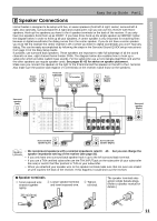
Connecting Your Equipment Connecting Video Components Before making or changing the connections, switch off the power and disconnect the power cord from the AC outlet. Connect your video components as shown on this and the following page. For video components (for example, a DVD player) there are two types of connections to make, video and audio. Hook up your video signal with either component video, S video or composite video cords (the quality descends in this order) but you must use the same type of cord as you used to hook up your TV. For the audio signal, in order to use digital soundtracks like Dolby Digital or DTS you must hook up a digital input, with either a coaxial or optical cord (see page 21). It is also a good idea to hook up your components with analog audio connections as well. If you want to record from your DVD player composite (or S video) cord connections and analog audio connections are necessary. Connecting a DVD player Before making or changing the connections, switch off the power and disconnect the power cord from the AC outlet. Hook up your audio signal with either a coaxial or optical digital cords (you don't need to do both). If you hook up your DVD/LD player using component video cable connections you might need to setup your DVD player for component video output as well. See your DVD manual for details. If you have a DVDAudio or Super Audio CD (SACD) compatible player, see "Connecting to the Multi Channel Analog Inputs" on page 20. You need to hook up your audio with analog connections as well. *The arrows indicate the direction of the signal. ASSIGNABLE PCM/ 2DIGITAL / DTS FM UNBAL 75Ω OUT1 IN OUT OUT2 CONTROL R L IN 1 PLAY (TV/ SAT) IN IN 2 CD-R/ (CD-R/ TAPE1 TAPE1) OUT REC IN 3 (DVD/ LD) IN 4 (CD) PLAY IN MD/ TAPE2 OUT REC CD IN DIGITAL LINE IN R L AUDIO AM LOOP ANTENNA PRE OUT CENTER SUB WOOFER ASSIGNABLE MONITOR OUT Y PB MONITOR OUT R L AUDIO FRONT IN VCR1/ DVR OUT IN VCR2 OUT TV/ SAT IN R SURROUND R SURROUND BACK R FRONT R SURROUND R SUB WOOFER L L (Single) L L L CEN- TER DVD/ LD IN SURROUND BACK R L VIDEO S VIDEO VIDEO MULTI CH IN PR (DVD/LD) IN 1 Y PB PR (TV/SAT) IN 2 Y PB PR COMPONENT VIDEO DIGITAL OUT 1 (not a PCM-only output) 23 VIDEO COMPONENT VIDEO OUT Y S-VIDEO PB PR ANALOG AUDIO L R DVD player memo • Be sure to make either a digital coaxial or digital optical connection (pictured as DIGITAL jack 3 or DIGITAL jack 2 in this diagram) but you DON'T need to make both. • If your digital connections are different than the default settings you will need to assign the digital jacks to the proper component(s) with the "Assigning the Digital Inputs" procedure. See page 76 to do this. • If your component video connections are different from the default settings, you will need to assign them with "Assigning the Component Video Inputs". See page 77 for how to do this. 16
-
 1
1 -
2
-
3
-
4
-
5
-
6
-
7
-
8
-
9
-
10
-
 11
11 -
 12
12 -
 13
13 -
 14
14 -
 15
15 -
 16
16 -
 17
17 -
 18
18 -
 19
19 -
 20
20 -
 21
21 -
22
-
23
-
24
-
25
-
26
-
27
-
28
-
29
-
30
-
31
-
32
-
33
-
34
-
35
-
36
-
37
-
38
-
39
-
40
-
41
-
42
-
43
-
44
-
45
-
46
-
47
-
48
-
49
-
50
-
51
-
52
-
53
-
54
-
55
-
56
-
57
-
58
-
59
-
60
-
61
-
62
-
63
-
64
-
65
-
66
-
67
-
68
-
69
-
70
-
71
-
72
-
73
-
74
-
75
-
76
-
77
-
78
-
79
-
80
-
81
-
82
-
83
-
84
-
85
-
86
-
87
-
88
-
89
-
90
-
91
-
92
-
93
-
94
-
95
-
96
-
97
-
98
-
99
-
100
-
101
-
102
-
103
-
104
 |
 |
