Sharp XG-C55X XG-C55X Operation Manual - Page 14
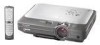
Part Names, Projector (Front and Top View) - remote
 |
UPC - 074000364219
View all Sharp XG-C55X manuals
Add to My Manuals
Save this manual to your list of manuals |
Page 14 highlights
Part Names Numbers in refer to the main pages in this operation manual where the topic is explained. Projector (Front and Top View) ON button 34 For turning the power on. Power indicator 34 Illuminates red, when the projector is in standby. When the power is turned on, this indicator will illuminate green. STANDBY button 37 For putting the projector into the standby mode. Lamp indicator 83 Illuminates green indicating normal function. Replace the lamp when the indicator illuminates red. Temperature warning 83 indicator When the internal temperature rises, this indicator will illuminate red. UNDO button 39 For undoing an operation or returning to the default settings. STANDBY 35 INPUT button For switching input mode 1, 2, 3 or 4. 38 KEYSTONE button For adjusting Keystone or Digital Shift setting. 50 AUTO SYNC button For automatically adjusting images when connected to a computer. 42 Adjustment buttons For selecting menu items. 35 VOLUME buttons For adjusting the speaker sound level. 42 MENU button For displaying adjustment and setting screens. 42 ENTER button For setting items selected or adjusted on the menu. HEIGHT ADJUST 25 button Adjustment foot 25 Carrying handle -10 Attaching and removing the lens cap • Press on the two buttons of the lens cap and attach it on the lens. Then release the buttons to lock it in place. • Press on the two buttons of the lens cap and remove it from the lens. 26 Zoom knob 26 Focus ring 80 Intake vent 13 Remote control sensor 81 Air filter/cooling fan (Intake vent) (on the bottom of the projector) In this operation manual, the illustration and the screen display are simplified for explanation, and may differ slightly from actual display.
-
 1
1 -
2
-
3
-
4
-
5
-
6
-
7
-
8
-
 9
9 -
 10
10 -
 11
11 -
 12
12 -
 13
13 -
 14
14 -
 15
15 -
 16
16 -
 17
17 -
 18
18 -
 19
19 -
20
-
21
-
22
-
23
-
24
-
25
-
26
-
27
-
28
-
29
-
30
-
31
-
32
-
33
-
34
-
35
-
36
-
37
-
38
-
39
-
40
-
41
-
42
-
43
-
44
-
45
-
46
-
47
-
48
-
49
-
50
-
51
-
52
-
53
-
54
-
55
-
56
-
57
-
58
-
59
-
60
-
61
-
62
-
63
-
64
-
65
-
66
-
67
-
68
-
69
-
70
-
71
-
72
-
73
-
74
-
75
-
76
-
77
-
78
-
79
-
80
-
81
-
82
-
83
-
84
-
85
-
86
-
87
-
88
-
89
-
90
-
91
-
92
-
93
-
94
-
95
-
96
-
97
-
98
-
99
-
100
-
101
-
102
-
103
-
104
-
105
-
106
 |
 |
