Sony FWD-42PV1 Operating Instructions - Page 10
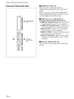
Connector Panel Left side
 |
View all Sony FWD-42PV1 manuals
Add to My Manuals
Save this manual to your list of manuals |
Page 10 highlights
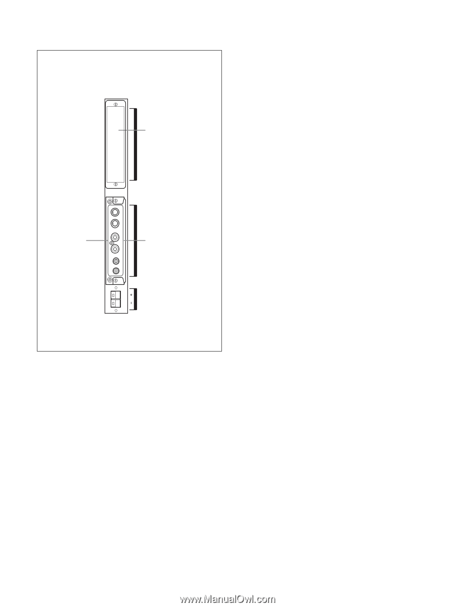
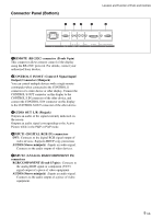
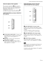
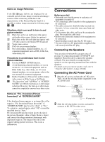
Location and Function of Parts and Controls Connector Panel (Left side) 6 COMMUNICATION Slot COMMUNICATION 7 8 OPTION1 (VIDEO/COM) Slot OPTION 1 (VIDEO/COM) 6COMMUNICATION slot This slot supports commucation function. A blank panel is attached to this slot for the factory setting. When you install the optional adaptor BKM-FW32 (Network Management Adaptor) in this slot, you can control the display unit via the network. 7VIDEO connectors (A BKM-FW10 is preinstalled only in the FWD-42LX1/32LX1.) S VIDEO IN (Mini DIN 4-pin) : Connects to the Y/ C signal output of a piece of video equipment. S VIDEO OUT (Mini DIN 4-pin) : Connects to the Y/C signal input of a piece of video equipment. VIDEO IN (BNC) : Connects to the video signal output of a piece of video equipment. VIDEO OUT (BNC) : Connects to the video signal input of a piece of video equipment. AUDIO IN L/R (Pinjack) : Inputs an audio signal. Connects to the audio output of a piece of video equipment. 8OPTION1 (VIDEO/COM) slot This slot supports video signals and communication function. SPEAKER L 10 (GB)
-
 1
1 -
2
-
3
-
4
-
 5
5 -
 6
6 -
 7
7 -
 8
8 -
 9
9 -
 10
10 -
 11
11 -
 12
12 -
 13
13 -
 14
14 -
 15
15 -
16
-
17
-
18
-
19
-
20
-
21
-
22
-
23
-
24
-
25
-
26
-
27
-
28
-
29
-
30
-
31
-
32
-
33
-
34
-
35
-
36
-
37
-
38
-
39
-
40
-
41
-
42
-
43
-
44
-
45
-
46
-
47
 |
 |