Sony FWD-42PV1 Operating Instructions - Page 11
Y/G P, R IN BNC, HD VD IN, AUDIO Stereo minijack, RGB/COMPONENT IN D-sub 15-pin, RGB/COMPONENT OUT D - no power
 |
View all Sony FWD-42PV1 manuals
Add to My Manuals
Save this manual to your list of manuals |
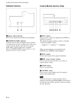
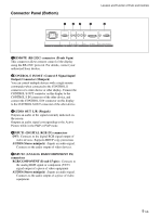
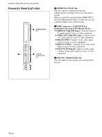
Page 11 highlights
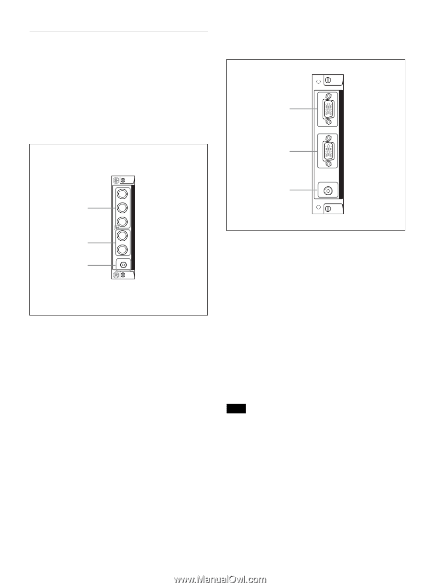
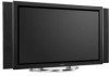
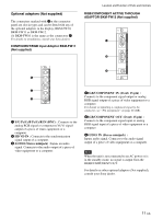
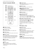
Optional adaptors (Not supplied) The connectors marked with 7on the connector panel are slot-in types and can be fitted with any of the optional adaptors in the display; BKM-FW10, BKM-FW11 or BKM-FW12. (A BKM-FW10 is the same as the connectors 7.) For details on installation, consult your Sony dealers. COMPONENT/RGB Input Adaptor BKM-FW11 (Not supplied) Location and Function of Parts and Controls RGB/COMPONENT ACTIVE THROUGH ADAPTOR BKM-FW12 (Not supplied) 1 2 IN RGB/COMPONENT THROUGH OUT AUDIO IN Y/G COMPONENT/RGB INPUT ADAPTOR 3 1 PR/CR/R PB/CB/B HD 2 3 1 Y/G PB/CB/B PR/CR/R IN (BNC) : Connects to the analog RGB signal or component (YUV) signal output of a piece of video equipment or a computer. 2 HD VD IN : Connects to the synchronization signal output of a computer. 3 AUDIO (Stereo minijack) : Inputs an audio signal. Connects to the audio output of a piece of video equipment or a computer. AUDIO VD 1RGB/COMPONENT IN (D-sub 15-pin) : Connects to the component signal output or analog RGB signal output of a piece of video equipment or a computer. For details on inputting a component signal to the connector, see "Pin assignment" on page 46 (GB). 2RGB/COMPONENT OUT (D-sub 15-pin) : Connects to the component signal input or analog RGB signal input of a piece of video equipment or a computer. 3AUDIO IN (Stereo minijack) : Inputs audio signal. Connects to the audio signal output of a piece of video equipment or a computer. Note When the unit is not connected to an AC power or is in the standby mode, no signal is output from the RGB/COMPONENT OUT. For details on other optional adaptors (Not supplied), consult your Sony dealer. 11 (GB)
-
 1
1 -
2
-
3
-
4
-
5
-
 6
6 -
 7
7 -
 8
8 -
 9
9 -
 10
10 -
 11
11 -
 12
12 -
 13
13 -
 14
14 -
 15
15 -
 16
16 -
17
-
18
-
19
-
20
-
21
-
22
-
23
-
24
-
25
-
26
-
27
-
28
-
29
-
30
-
31
-
32
-
33
-
34
-
35
-
36
-
37
-
38
-
39
-
40
-
41
-
42
-
43
-
44
-
45
-
46
-
47
 |
 |