Sony FWD-42PV1 Operating Instructions - Page 7
Location and Function, of Parts and Controls
 |
View all Sony FWD-42PV1 manuals
Add to My Manuals
Save this manual to your list of manuals |
Page 7 highlights
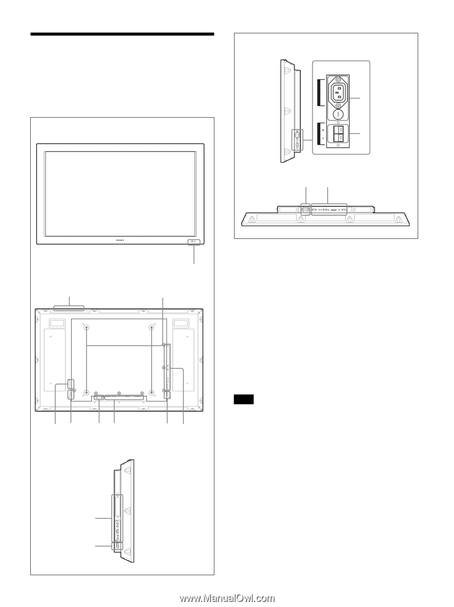
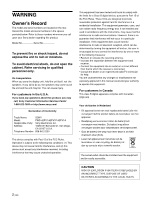
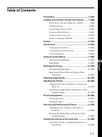
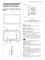
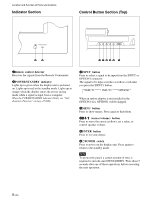
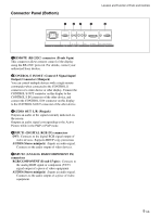
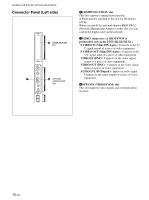
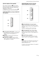
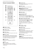
Location and Function of Parts and Controls Front / Rear / Left side / Right side / Bottom Front AC OUT Location and Function of Parts and Controls Right side 4 5 SPEAKER R Bottom 67 Rear 2 45 Left side 67 7 5 1 3 57 1Indicator section For details on the Indicator section, see "Indicator Section" on page 8 (GB). 2Control button section For details on the control button section, see "Control Button Section (Top)" on page 8 (GB). 3Stand installation hooks Use these hooks to install the stand (not supplied). 4AC OUT socket (three brade type) You can connect a device consuming small power to this socket and supply power when setting up an audio/visual system (the power rating: maximum 0.5 A). For more details, consult your Sony dealer. Note Be sure not to connect the device of which power consumption exceeds its rating. 5SPEAKER Socket Connects the speakers (not supplied) to this socket to output the audio matching the signal displayed on the screen. 6- AC IN socket Connect the supplied AC power cord to this socket and to a wall outlet. Once you connect the AC power cord, the POWER/STANDBY indicator lights up in red and the display goes into the standby mode. For more details on the power cord, see "Connecting the AC Power Cord" on page 15 (GB). 7Connector panel For details on the connector panel, see "Connector Panel (Bottom)" on page 9 (GB) and "Connector Panel (Left side)" on page 10 (GB). 7 (GB)
-
 1
1 -
 2
2 -
 3
3 -
 4
4 -
 5
5 -
 6
6 -
 7
7 -
 8
8 -
 9
9 -
 10
10 -
 11
11 -
 12
12 -
13
-
14
-
15
-
16
-
17
-
18
-
19
-
20
-
21
-
22
-
23
-
24
-
25
-
26
-
27
-
28
-
29
-
30
-
31
-
32
-
33
-
34
-
35
-
36
-
37
-
38
-
39
-
40
-
41
-
42
-
43
-
44
-
45
-
46
-
47
 |
 |