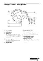
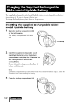
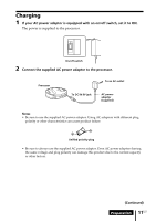
Sony MDR DS6000 Operating Instructions - Page 7
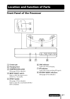
Location and Function of Parts, Front Panel of the Processor - compression
 |
UPC - 027242680722
View all Sony MDR DS6000 manuals
Add to My Manuals
Save this manual to your list of manuals |
Page 7 highlights
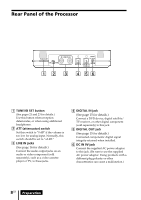
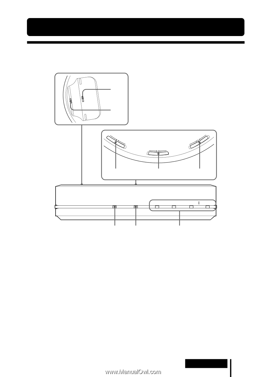
Location and Function of Parts Front Panel of the Processor 1 2 OFCFOMPRESSOIONN 3 INPUT SELECT ANALOG DIGITAL 4 MUSIECFOFEFCFTCINEMA 5 CHG RF DTS DOLBY DIGITAL DOLBY PRO LOGIC MPEG-2 AAC 67 8 1 Contact pin 2 Charging lever 3 COMPRESSION switch (See page 20 for details.) 4 INPUT SELECT switch Slide to select the input source (DIGITAL/ANALOG). 5 EFFECT switch (See page 19 for details.) Slide to select the sound field (MUSIC/ OFF/CINEMA). 6 CHG indicator Lights red while charging. 7 RF indicator Lights blue while emitting RF signals. 8 DECODE MODE indicators (See page 20 for details.) Preparation 7US
-
 1
1 -
 2
2 -
 3
3 -
 4
4 -
 5
5 -
 6
6 -
 7
7 -
 8
8 -
 9
9 -
 10
10 -
 11
11 -
 12
12 -
13
-
14
-
15
-
16
-
17
-
18
-
19
-
20
-
21
-
22
-
23
-
24
-
25
-
26
-
27
-
28
-
29
-
30
-
31
-
32
-
33
-
34
-
35
-
36
-
37
-
38
-
39
-
40
-
41
-
42
-
43
-
44
-
45
-
46
-
47
-
48
-
49
-
50
-
51
-
52
-
53
-
54
-
55
-
56
-
57
-
58
-
59
-
60
-
61
-
62
-
63
-
64
-
65
-
66
-
67
-
68
-
69
-
70
-
71
-
72
-
73
-
74
-
75
-
76
-
77
-
78
-
79
-
80
-
81
-
82
-
83
-
84
-
85
-
86
-
87
-
88
-
89
-
90
-
91
-
92
 |
 |
Preparation
7
US
Front Panel of the Processor
CHG
RF
DTS
DOLBY DIGITAL
DOLBY PRO LOGIC
MPEG-2 AAC
6
3
1
2
4
5
L
A
T
I
G
I
D
G
O
L
A
N
A
A
M
E
N
I
C
F
F
O
C
I
S
U
M
N
O
F
F
O
T
C
E
L
E
S
T
U
P
N
I
T
C
E
F
F
E
N
O
I
S
S
E
R
P
M
O
C
7
8
Location and Function of Parts
1
Contact pin
2
Charging lever
3
COMPRESSION switch
(See page 20
for details.)
4
INPUT SELECT switch
Slide to select the input source
(DIGITAL/ANALOG).
5
EFFECT switch
(See page 19
for details.)
Slide to select the sound field (MUSIC/
OFF/CINEMA).
6
CHG indicator
Lights red while charging.
7
RF indicator
Lights blue while emitting RF signals.
8
DECODE MODE indicators
(See page 20
for details.)