Sony MDR DS6000 Operating Instructions - Page 8
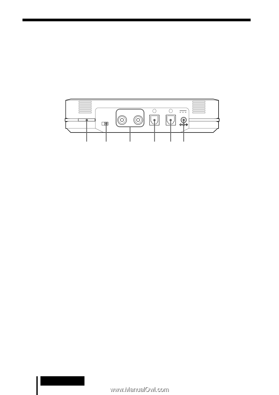
Rear Panel of the Processor, TUNE/ID SET button, ATT attenuator switch, LINE IN jacks, DIGITAL IN jack - - headphones
 |
UPC - 027242680722
View all Sony MDR DS6000 manuals
Add to My Manuals
Save this manual to your list of manuals |
Page 8 highlights
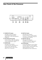
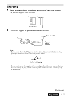
Rear Panel of the Processor TUNE/ID SET ATT 0dB -8dB R LINE IN L DC IN 9V DIGITAL IN DIGITAL OUT (THROUGH) 1 2 3 4 56 1 TUNE/ID SET button (See pages 21 and 23 for details.) Use this button when reception deteriorates, or when using additional headphones. 2 ATT (attenuator) switch Set this switch to "0 dB" if the volume is too low for analog input. Normally, this switch should be set to "-8 dB." 3 LINE IN jacks (See page 16 for details.) Connect the audio output jacks on an audio or video component (sold separately), such as a video cassette player or TV, to these jacks. 4 DIGITAL IN jack (See page 15 for details.) Connect a DVD device, digital satellite/ TV receiver, or other digital component (sold separately) to this jack. 5 DIGITAL OUT jack (See page 15 for details.) Connected components' digital signal integrity retained when installed. 6 DC IN 9V jack Connect the supplied AC power adaptor to this jack. (Be sure to use the supplied AC power adaptor. Using products with a different plug polarity or other characteristics can cause a malfunction.) 8US Preparation
-
 1
1 -
2
-
 3
3 -
 4
4 -
 5
5 -
 6
6 -
 7
7 -
 8
8 -
 9
9 -
 10
10 -
 11
11 -
 12
12 -
 13
13 -
14
-
15
-
16
-
17
-
18
-
19
-
20
-
21
-
22
-
23
-
24
-
25
-
26
-
27
-
28
-
29
-
30
-
31
-
32
-
33
-
34
-
35
-
36
-
37
-
38
-
39
-
40
-
41
-
42
-
43
-
44
-
45
-
46
-
47
-
48
-
49
-
50
-
51
-
52
-
53
-
54
-
55
-
56
-
57
-
58
-
59
-
60
-
61
-
62
-
63
-
64
-
65
-
66
-
67
-
68
-
69
-
70
-
71
-
72
-
73
-
74
-
75
-
76
-
77
-
78
-
79
-
80
-
81
-
82
-
83
-
84
-
85
-
86
-
87
-
88
-
89
-
90
-
91
-
92
 |
 |