Sony SRPC4 Product Manual (SRMASTER: SRPC4 / SRPC5 Operation Manual) - Page 24
SR-PC4, Appendix, Error/Warning Messages
 |
View all Sony SRPC4 manuals
Add to My Manuals
Save this manual to your list of manuals |
Page 24 highlights
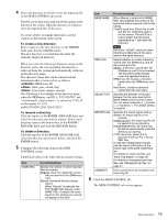
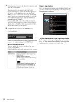
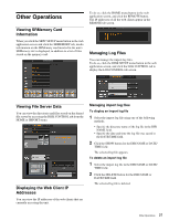
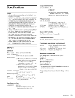
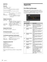
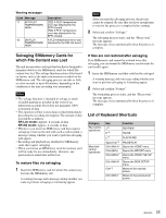
SR-PC4 General Power supply 19.5 V Currnet consumption 5 A (with all options installed) Operating temperature 5 °C to 35 °C (41 °F to 95 °F) Storage temperature -20 °C to +60 °C (-4 °F to +140 °F) Mass Dimensions 3.9 kg (8 lb. 10 oz.) 88 × 250 × 9 1/8 in.) 231 mm (3 (W×H×D) 1/2 × 9 7/8 × (excluding protrusions) Appendix Error/Warning Messages When an abnormality is detected on the unit, a yellow warning mark ( ) flashes to the left of the timecode (or picture ID) in the MEM CONTROL window. Clicking the warning mark displays the message as follows. Output connectors MONITOR NETWORK Option BNC (1) HD SDI (1.485 Gbps) (conforming to SMPTE-292M, BTA-S004B) 3G SDI (2.97 Gbps) (SMPTE-424M) 1000Base-T modular jack (1) PCI Express Slot (1) (PCI Express x4 Gen1) Supported formats See "Supported Formats" on page 26. On-board functions 1D LUT, downconverter, color space converter Confirmed operational environment Browser NFS server CIFS server Firefox, Internet Explorer, Safari, Google Chrome Redhat Linux E5, Mac OS v10.6 Windows XP, Windows 7 Supplied accessories AC adapter (1) Rubber feet (4) SR Viewer (CD-ROM) (1) Installation manual (1) Operation guide (1) Operation manual (CD-ROM) (1) Design and specifications are subject to change without notice. Error messages Code Message Description 03 FAN STOP A fan error was detected. 04 POWER FAN STOP [PC5] An error was detected with the fan located in the power section. 81 EPR PLD1 INITIAL [PC5] A PLD1 initialization error ERROR was detected for the EPR-3 board. [PC4] A PLD1 initialization error was detected for the EPR-4 board. 82 EPR PLD2 INITIAL [PC5] A PLD2 initialization error ERROR was detected for the EPR-3 board. [PC4] A PLD2 initialization error was detected for the EPR-4 board. 83 CN PLD1 INITIAL [PC5] A PLD1 initialization error ERROR was detected for the CN-3367 board. 83 DC PLD1 INITIAL [PC4] A PLD1 initialization error ERROR was detected for the DC-161 board. 84 DM INTERFACE A communication error was ERROR detected between the DM-145 and CPU. 88 NVRAM CHECKSUM ERROR An NVRAM (IC310) checksum error was detected. IP address and other configuration data may be damaged. Restart the unit using the factory default settings (IP address: 192.168.0.1; subnet mask: 255.255.255.0; MTU: 1500). 24 Appendix
-
 1
1 -
2
-
3
-
4
-
5
-
6
-
7
-
8
-
9
-
10
-
11
-
12
-
13
-
14
-
15
-
16
-
17
-
18
-
 19
19 -
 20
20 -
 21
21 -
 22
22 -
 23
23 -
 24
24 -
 25
25 -
 26
26 -
 27
27 -
 28
28 -
 29
29 -
30
-
31
 |
 |