Sony SRPC4 Product Manual (SRMASTER: SRPC4 / SRPC5 Operation Manual) - Page 9
Names and Functions of Parts, Front
 |
View all Sony SRPC4 manuals
Add to My Manuals
Save this manual to your list of manuals |
Page 9 highlights
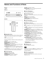
Names and Functions of Parts Front SRPC-5 1 234 56 7 SR-PC4 6 1 7 2 4 8 a On/standby button [PC5] When the main power switch on the rear of the unit is turned on, this turns on the unit or sets it to standby mode. [PC4] Turns the unit on/off. The button will light or blink based on the operating status of the unit. Lit red: The unit is in standby mode. Blinking green: The unit is starting up. Lit green: The unit is turned on. Blinking green: If the button blinks green after startup, the unit may be malfunctioning. Blinking red: [PC4] If the button is blinking red before the unit is turned on, the power supply voltage may be incorrect. If the button blinks green after startup or blinks red, stop operation and contact your local Sony representative. b STATUS indicator Displays the status of the unit. Lit green: Operating normally. Blinking green: The unit is starting up. Lit yellow: A warning has occurred. Lit red: An error has occurred. Blinking blue: The unit is starting up in default IP address mode (see page 12). c [PC5] VTR indicator This is not used in this version. d NETWORK indicator Displays the communication status between the unit and the server. Off: The server is not mounted. Lit green: The server is mounted. Blinking green: Data is being transferred. e [PC5] Eject button Press this to eject the SRMemory card. f SRMemory indicator Displays the status of the SRMemory card inserted in the slot. Off: The SRMemory card is logically detached from the unit. Lit blue: The SRMemory card is connected to the unit and available for use. Lit green: Data is being read from the SRMemory card. Blinking blue1): The SRMemory card is logically being attached to or detached from the unit. Blinking green1): Data other than audio and video signals, such as file name changes, is being written. Blinking purple1): Files are being deleted or formatting is being performed from the menu. Blinking red1): Salvaging or formatting is being performed in response to an error. Fast blinking red1): A problem was detected while processing the SRMemory card. Eject or salvage the card or perform the appropriate operation as instructed by the message that appears. 1) Blinking LED: Blinks at 1-second interval. Fast blinking LED: Blinks at 1/4-second interval. g SRMemory slot Insert the SRMemory card here. Note [PC4] Be sure to insert the SRMemory card all the way into the slot. The card may not lock into place if it is not inserted completely. h [PC4] UNLOCK button Unlocks the SRMemory slot. Press this button to unlock the slot before removing an SRMemory card. 9 Names and Functions of Parts
-
 1
1 -
2
-
3
-
 4
4 -
 5
5 -
 6
6 -
 7
7 -
 8
8 -
 9
9 -
 10
10 -
 11
11 -
 12
12 -
 13
13 -
 14
14 -
15
-
16
-
17
-
18
-
19
-
20
-
21
-
22
-
23
-
24
-
25
-
26
-
27
-
28
-
29
-
30
-
31
 |
 |
