Sony VPL-CS7 User Manual - Page 18
Connecting with a VCR, Ex. VPL-ES2 - projectors
 |
View all Sony VPL-CS7 manuals
Add to My Manuals
Save this manual to your list of manuals |
Page 18 highlights
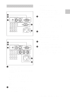
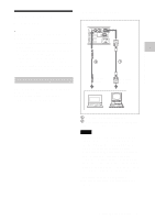
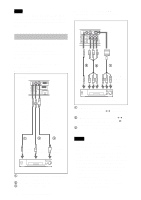
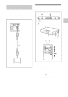
Note To connect a Macintosh computer equipped with video output connector of a type having two rows of pins, use a commercially available plug adaptor. To connect to a video GBR/ component output connector Ex. VPL-ES2 Left side Connecting with a VCR This section describes how to connect the projector to a VCR. For more information, refer to the instruction manuals of the equipment you are connecting. To connect to a video or S video output connector Ex. VPL-CS7 Left side AUDIO AUDIO VIDEO S VIDEO INPUT A MONITOR OUT AUAUDDIIOO VIDEO S VIDEO INPUT A PR/CR PB/CB Y 32 to audio output 1 to RGB/ component output 1 2 3 to audio output to video output to S video output VCR 1Stereo audio connecting cable (not supplied) (Use a no-resistance cable) 2Video cable (not supplied) or 3S-Video cable (not supplied) 18 Connecting the Projector 15k RGB/Component equipment 1SMF-402 Signal Cable (not supplied) HD D-sub 15-pin (male) y 3 × phono plug or 2Component video (3 × phono plug y 3 × phono plug (not supplied) (Use a 75 Ω coaxial cable) (VPL-ES2 only)) 3Stereo audio connecting cable (not supplied) (Use a no-resistance cable) Notes • Set the aspect ratio using "Wide Mode" in the INPUT SETTING menu according to the input signal. • When you connect the INPUT A connector on the unit to a video GBR output connector, select "Video GBR," or when you connect it to a component output connector, select "component" with the "Input-A Signal Sel." setting in the SET SETTING menu. The input selection must be performed before inputting the signal. • Use the composite sync signal when you input the external sync signal from video GBR/component equipment.
-
 1
1 -
2
-
3
-
4
-
5
-
6
-
7
-
8
-
9
-
10
-
11
-
12
-
 13
13 -
 14
14 -
 15
15 -
 16
16 -
 17
17 -
 18
18 -
 19
19 -
 20
20 -
 21
21 -
 22
22 -
 23
23 -
24
-
25
-
26
-
27
-
28
-
29
-
30
-
31
-
32
-
33
-
34
-
35
-
36
-
37
-
38
-
39
-
40
-
41
-
42
-
43
-
44
-
45
-
46
-
47
-
48
-
49
-
50
-
51
-
52
-
53
-
54
 |
 |
