Stihl FSA 86 R Instruction Manual - Page 22
Assembling the Trimmer
 |
View all Stihl FSA 86 R manuals
Add to My Manuals
Save this manual to your list of manuals |
Page 22 highlights
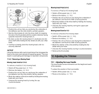
English 10.2.2 Power Tool Status When the battery is connected to the power tool, the same LEDs on the battery will indicate the status of the power tool. If three LEDs glow red continuously: the power tool motor is too hot. Allow the motor to cool down. If three LEDs flash red when you activate the trigger switch: the power tool has an electrical malfunction. Do not operate the power tool. Have it checked by an authorized STIHL servicing dealer before use or storage. For troubleshooting information, @ 22. 10.2.3 Charge Status The LEDs and acoustic signals on the battery also indicate the battery's state of charge. To determine the battery's state of charge: 11 Assembling the Trimmer 11 Assembling the Trimmer 11.1 Mounting the Loop Handle WARNING To reduce the risk of injury from loss of control, ensure that the loop handle is properly and securely mounted before starting work. To mount the loop handle: ► Switch off the power tool, @ 14.2. ► Remove the battery, @ 13.2. 1 2 3 100 % 0 % ► Press the button (1) on the backpack battery. A single short beep will be emitted. The LEDs on the battery will glow or flash green for about 5 seconds and indicate the state of charge (see illustration). For example: If six green LEDs glow continuously: full charge. If one green LED is flashing and four long beeps are emitted: less than 20 % charge. 0000-GXX-2673-A0 0000097536_001 4 5 6 7 ► Position one clamp (4) in the loop handle (3). ► Position the other clamp (6) against the underside of the drive tube (5) and line up the holes in the loop handle and clamps. ► Put washers (2) on the screws (1) and insert the screws through the holes in the loop handle and clamps. ► Attach the square nuts (7) and tighten securely. Ensure that the handle is tight and will not move during operation. 11.2 Mounting the Bump Guard To mount the bump guard: ► Switch off the power tool, @ 14.2. ► Remove the battery, @ 13.2. 20 0458-833-8621-A
-
 1
1 -
2
-
3
-
4
-
5
-
6
-
7
-
8
-
9
-
10
-
11
-
12
-
13
-
14
-
15
-
16
-
 17
17 -
 18
18 -
 19
19 -
 20
20 -
 21
21 -
 22
22 -
 23
23 -
 24
24 -
 25
25 -
 26
26 -
 27
27 -
28
-
29
-
30
-
31
-
32
-
33
-
34
-
35
-
36
-
37
-
38
-
39
-
40
-
41
-
42
-
43
-
44
-
45
-
46
-
47
-
48
-
49
-
50
-
51
-
52
-
53
-
54
-
55
-
56
-
57
-
58
-
59
-
60
-
61
-
62
-
63
-
64
-
65
-
66
-
67
-
68
-
69
-
70
-
71
-
72
-
73
-
74
-
75
-
76
-
77
-
78
-
79
-
80
 |
 |
