Thermador PRD486JDGU Installation Manual
Thermador PRD486JDGU Manual
 |
View all Thermador PRD486JDGU manuals
Add to My Manuals
Save this manual to your list of manuals |
Thermador PRD486JDGU manual content summary:
- Thermador PRD486JDGU | Installation Manual - Page 1
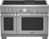
INSTALLATION MANUAL For THERMADOR PROFESSIONAL PRO GRAND® Dual Fuel Ranges MANUEL D'INSTALLATION Pour cuisinières mixtes PROFESSIONAL PRO GRANDmc de THERMADOR Models/ Modèles / Modelos: PRD36 PRD48 MANUAL DE INSTALACIÓN Para estufas mixtas PROFESSIONAL PRO GRAND® de THERMADOR - Thermador PRD486JDGU | Installation Manual - Page 2
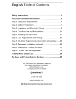
(optional 19 Step 9: Placing and Leveling the Range 25 Step 10: Burner Test and Adjustment 29 Installer Final Check List 30 To Clean and Protect Exterior Surfaces 30 This THERMADOR® appliance is made by BSH Home Appliances Corporation 5551 McFadden Ave. Huntington Beach, CA 92649 Questions - Thermador PRD486JDGU | Installation Manual - Page 3
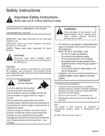
APPROVED FOR ALL RESIDENTIAL APPLIANCES FOR RESIDENTIAL USE ONLY IMPORTANT: Save these Instructions for the Local Gas Inspector's use. INSTALLER: Please leave these Installation Instructions with this unit for the owner. OWNER: Please retain these instructions for future reference. WARNING - Thermador PRD486JDGU | Installation Manual - Page 4
with natural gas. Field conversion of the appliance for use with propane gas supply will require installation of conversion kit supplied with the range (service number 553182). Only a qualified service technician or installer should make this conversion. See LP Conversion Kit instructions for full - Thermador PRD486JDGU | Installation Manual - Page 5
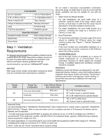
burners with griddle 1200 (cfm) 48" or 54" Pro Wall Hood 48" Custom Insert w/ optional blower Important Notes: It is recommended that a THERMADOR PROFESSIONAL® wall or island hood or custom insert is used with THERMADOR PROFESSIONAL® Ranges. Refer to www.thermador.com for a complete selection of - Thermador PRD486JDGU | Installation Manual - Page 6
range above the cooking surface, a THERMADOR® Low Back or High Shelf must be installed (see Figure 2, page 6). When clearance to combustible material is over 12" (305mm), the supplied THERMADOR not install the range such that the oven door is flush with the cabinet face. A flush installation could - Thermador PRD486JDGU | Installation Manual - Page 7
Depth Range width 36" (914mm) or 48" (1219mm) 5" (127mm) min. to combustible sidewall material (both sides). CAUTION! See Figure 2 36" (914mm) Min. to combustible material from cooking Surface For Electrical & Gas Supply zones, see Figure 3. Zone sizes & positions differ according to model. Gas - Thermador PRD486JDGU | Installation Manual - Page 8
minimum recess depth 281/2" (723mm) 483/4" (1238mm) Installation with Included Flush Island Trim 36" (914mm) min to combustible materials 12" (305mm) Min to Combustible with Flush Island Trim 1/8" (3mm) gap from the rear of the range to the inner wall. FIGURE 2: SIDE VIEW OF CLEARANCES - Thermador PRD486JDGU | Installation Manual - Page 9
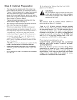
(76mm) 2" (51mm) A B C D 36" (913mm) 48" (1219mm) Notice: • If not already present, install gas shut-off valve in an easily accessible location. • Make sure all users know where and how to shut off the gas supply to the range. • Any opening in the wall behind the appliance and any opening in - Thermador PRD486JDGU | Installation Manual - Page 10
appliance. The range has an approximate shipping weight as shown in "Chart A". The grates, griddle plate, burner caps, and oven finish from scratches, until the range is installed in its final position. 2. and oven racks 36" Range 420 lbs (191 kg) 360 lbs (163 kg) 260 lbs (118 kg) 48" Range 590 - Thermador PRD486JDGU | Installation Manual - Page 11
uniformly across the bottom (see Figure 6). • After transporting the range by dolly close to its final location, the range can be tipped back and supported on the rear casters while the dolly is carefully removed. • "Step 5: Installing Anti-Tip Device", "Step 6: Gas Requirements and Hookup", "Step - Thermador PRD486JDGU | Installation Manual - Page 12
try to close the hinges. Without the weight of the door, the powerful springs will snap the hinges closed with great force. To Remove the Oven Door: 1. Open the door fully and use a screwdriver to carefully pry the hinge clips away from the hinge slots (Photo A). 2. Flip the hinge clip toward - Thermador PRD486JDGU | Installation Manual - Page 13
to test the movement and the fit of the door to the oven cavity. Do not force the door to open or close. If the door is properly installed, it should move smoothly and rest straight on the front of the range when closed. 2. If the door does not operate correctly, verify that - Thermador PRD486JDGU | Installation Manual - Page 14
tip-over may exist and injury can result if the appliance is not installed in accordance with these instructions. For all ranges an anti-tip device must be installed as per these instructions. • If the range is pulled away from the wall for cleaning, service or for any other reason, ensure that the - Thermador PRD486JDGU | Installation Manual - Page 15
the unit is to be finally located (shown in Figure 8). • If the range is moved to a new location, the Anti-Tip Device must be reinstalled. 2. to the floor using the screws provided. 3. Later, when the unit is installed, the adjustable legs will allow the cast base to slide under the bracket hook - Thermador PRD486JDGU | Installation Manual - Page 16
of the appliance for use with propane gas supply will require installation of the conversion kit supplied with the range (service number 553182). A qualified technician or installer must do the conversion. See LP Conversion Kit instructions for full installation information. Obey all instructions in - Thermador PRD486JDGU | Installation Manual - Page 17
A manual gas shut-off valve must be installed external to the appliance, in a location accessible from the front, for the purpose of shutting off the gas supply. The supply line must not interfere with the back of the unit. The range is supplied with its own pressure regulator that has been - Thermador PRD486JDGU | Installation Manual - Page 18
fuse. Lock service panel to prevent power from being turned ON accidentally. Dual Fuel range models can be connected or hardwired to the power supply as described on page 17. MODEL TYPE 36" 48" Chart B: Electrical Supply Circuit Requirements VOLTAGE 240/208 VAC 240/208 VAC CIRCUIT RATING 40 Amps - Thermador PRD486JDGU | Installation Manual - Page 19
12). If aluminum supply wiring exists in the installation, splice the aluminum house wiring with appropriate-thickness gauge copper wire for adapting to the range CORD KIT RATED 125/250 VOLTS, 50 AMPERES, AND MARKED FOR USE WITH RANGES. The cord kit must be attached to the range terminal block with - Thermador PRD486JDGU | Installation Manual - Page 20
- WHERE LOCAL CODES AND ORDINANCES PERMIT GROUNDING THROUGH NEUTRAL, AND CONVERSION OF SUPPLY TO 4 WIRE IS IMPRACTICAL, UNIT MAY BE CONNECTED TO THE POWER SUPPLY WITH A 3-POLE, 3-CONDUCTOR CORD KIT RATED 125/250 VOLTS, 50 AMPERES, AND MARKED FOR USE WITH RANGES. The cord kit must be attached to the - Thermador PRD486JDGU | Installation Manual - Page 21
36", 48" (760mm, 913mm, 1218mm) (1) Backsplash Tape measure 42" (1070mm) (1) Installation Guide Pencil • To protect against scratches, leave protective film on backsplash until after installation is complete. • If range is already installed, refer to the manufacture's instructions to disconnect - Thermador PRD486JDGU | Installation Manual - Page 22
against scratches, leave protective film on the backsplash until after installation is complete. • If range is already installed, refer to the manufacture's instructions to disconnect gas and power supplies. Move range forward to gain access to rear of unit. IncLlouwdeedr SWhiethlf KBeraecpkHetost - Thermador PRD486JDGU | Installation Manual - Page 23
Keep Hot Shelf (KHS [30,36,42,48] QS) (16mm) 5/8" 137/8" (352mm) Items Included (12) 1" (25.4mm) screws (4) 1/2" (12.7mm) screws (4) U-Nuts (2) Top shelf brackets (73602",,93164",, 1420"6,74 brackets (2) Keep hot racks (1) Keep hot shelf backsplash (1) Installation guide & template English 21 - Thermador PRD486JDGU | Installation Manual - Page 24
with the top line of the template. • Tape the sheet titled Installation Instruction so that the arrow at the top of the template aligns with the wall. 7. Secure to bottom of shelf with the (4) 1/2" (12.7mm) screws provided. For 48" Keep Hot Shelf Follow steps 1-6 except use (4) lower brackets which - Thermador PRD486JDGU | Installation Manual - Page 25
Backguard Installation PRD364JDGU PRD364JDGC PRD366JGU PRD366JGC PRD486JDGU PRD486JDGC PRD48JDSGU PRD48JDSGC AVAILABLE FOR THESE MODELS: Pro Grand® 36" Dual Fuel Range 4 Burner Griddle Pro Grand® 36" Dual Fuel Range 4 Burner Griddle - Canadian Pro Grand® 36" Dual Fuel Range 6 Burner Pro Grand® 36" - Thermador PRD486JDGU | Installation Manual - Page 26
surfaces ∆ and the back edge of the range above the cooking surface, a THERMADOR® Low Back or High Shelf must be purchased separately and installed. When clearance to combustible surfaces ∆ is over 12" (305mm) or for island installations, the supplied THERMADOR® Flush Island Trim may be used. High - Thermador PRD486JDGU | Installation Manual - Page 27
that the oven cavities are also level for optimum cooking performance. • Each range has a pair of casters adjacent to the rear legs (see Figure 24). The casters make moving the range easier by slightly lifting the front and allowing the casters to glide the range back towards its installed position - Thermador PRD486JDGU | Installation Manual - Page 28
than the adjacent cabinet. This may damage the cabinet and countertop due to excessive temperatures. CORRECT! Leveling legs should be adjusted so that the range sides are at the same or higher level as the adjacent cabinet. English 26 Leveling legs can be adjusted by using an adjustable wrench on - Thermador PRD486JDGU | Installation Manual - Page 29
the range, wrap the mated pieces around the leg. 4. Slide the outer sleeve up while the inner piece remains on the floor. The mating part has visible legs. After the range is properly leveled and the leg covers have been installed, replace the Door Trim and reinstall the Oven Door(s) ("Step 4: Door - Thermador PRD486JDGU | Installation Manual - Page 30
should feel a definitive snap, letting you know that the part has been installed. 5. Mount the Toe Kick Panel on both sides of the unit into the extruded dimples using the (4) T-20 Torx drill point screws provided. (1) Installation Guide Tools Needed T-20 Torx head screwdriver or drill Protective - Thermador PRD486JDGU | Installation Manual - Page 31
Install any loose components, such as burner caps and grates, that may have been removed earlier. Be certain that burner caps seat properly into the burner bases. Before testing operation of the appliance over," call THERMADOR®. Four rangetop burners the XLO® range. This is normal Normal for LP Gas. - Thermador PRD486JDGU | Installation Manual - Page 32
: Write the model number and serial number found on the Rating Label Plate in the USE AND CARE MANUAL on page 32 (plate is located on the right side of the range between the oven cavity and side panel). Leave USE AND CARE MANUAL and the INSTALLATION MANUAL with the owner of the appliance. To Clean - Thermador PRD486JDGU | Installation Manual - Page 33
ère 8 Étape 4 : Retrait et installation de la porte 10 Étape 5 : Installation du dispositif anti-bascule 12 Étape 6 : Exigences relatives à l'approvisionnement BSH Home Appliances Corporation 5551 McFadden Av. Huntington Beach, CA 92649 Des questions? 1-800-735-4328 www.thermador.com Nous - Thermador PRD486JDGU | Installation Manual - Page 34
. • Appelez immédiatement votre société gazière chez un voisin et suivez les instructions qu'elle vous donne. • Si vous n'arrivez pas à contacter votre société gazière, appelez le service d'incendie. - L'installation et les travaux d'entretien doivent être réalisés par un installateur qualifié, un - Thermador PRD486JDGU | Installation Manual - Page 35
naturel ou au gaz propane (LP). Assurez-vous que la cuisiniè conversion. Consultez les instructions du jeu de conversion au propane pour obtenir tous les renseignements nécessaires à une installation installé dosseret bas ou une étagère haute THERMADORmc lorsque l'espace libre horizontal est inférieur à 12 - Thermador PRD486JDGU | Installation Manual - Page 36
Mèche de 3/16 po Mèche de 1/8 po (3,17 mm) Clé ajustable de 12 po (4,76 mm) Perceuse à main ou Ruban à mesurer électrique Tournevis plat et tape 1 : Exigences en matière de ventilation Il est fortement recommandé d'installer une hotte de ventilation appropriée au-dessus de la cuisinière. Une - Thermador PRD486JDGU | Installation Manual - Page 37
Hotte Pro Wall de 48 ou 54 po chauffante Garniture sur mesure de 48 po avec Remarques importantes : ventilateur optionnel Il est recommandé d'utiliser une hotte murale ou une hotte îlot, ou une garniture sur mesure THERMADOR PROFESSIONAL® avec les cuisinières THERMADOR PROFESSIONAL® Consultez - Thermador PRD486JDGU | Installation Manual - Page 38
hotte : 36 po (914 mm) ou 42 po (1067 mm) {Installation en îlot : 42 po (1067 mm) ou 48 po (1219 mm) Cuisinières de 48 po {Largeur de hotte : 48 po (1219 mm), 54 po (1372 mm) ou 60 po (1524 mm) {Installation en îlot : 54 po (1372 mm) Cuisinière de 36 po - Thermador PRD486JDGU | Installation Manual - Page 39
(911mm) Profondeur minimale pour encastrement: 251/8 po (638 mm) 281/2 po (723mm) 483/4 po (1238mm) Installation avec garniture d'ilot incluse 36 po (914mm) min jusqu'aux matériaux combustibles 12 po (305mm) Min jusqu'aux matériaux combustibles* avec garniture d'îlot Matériaux combustibles Note - Thermador PRD486JDGU | Installation Manual - Page 40
po (76mm) 2 po (51mm) A B C D 36 po (913mm) 48 po (1219mm) Figure 3: Emplacement des zones d'approvisionnement en gaz et d'alimentation en tre presque parfaitement alignée avec le mur arrière. Pour une installation réussie, il peut être nécessaire de repositionner le tuyau d' - Thermador PRD486JDGU | Installation Manual - Page 41
ce que la cuisinière soit installée à son emplacement définitif. 2. Enlevez la ou les portes (voir la section « Étape 4 : Retrait et installation de la porte »). Cela réduira (191 kg) 360 lbs (163 kg) 260 lbs (118 kg) Cuisinière de 48 po 590 lbs (268 kg) 530 lbs (240 kg) 390 lbs (177 kg) - Thermador PRD486JDGU | Installation Manual - Page 42
les deux vis qui la retiennent à la cuisinière, puis faites- la glisser vers le haut. • Suivez les instructions des sections « Étape 5 : Installation du dispositif anti-bascule », « Étape 6 : Exigences relatives à l'approvisionnement en gaz et au raccordement », « Étape 7 : Exigences relatives - Thermador PRD486JDGU | Installation Manual - Page 43
Étape 4 : Retrait et installation de la porte MISE EN GARDE: FAITES ATTENTION LORSQUE VOUS ENLEVEZ LA PORTE. ELLE EST TRÈS LOURDE. Pour éviter tout risque de brûlure ou - Thermador PRD486JDGU | Installation Manual - Page 44
Ne forcez pas pour l'ouvrir ou la fermer. Si la porte est bien installée, elle devrait être facile à ouvrir et être alignée avec le devant l'autre, vous pouvez ajuster l'inclinaison en vissant ou dévissant à l'aide d'un grand tournevis Torx T-20 la vis Torx de la charnière, située directement au- - Thermador PRD486JDGU | Installation Manual - Page 45
si le support est vissé support anti-bascule n'est pas installé et qu'il ne retient pas l'appareil. --La non-observation de ces instructions peut entraîner la mort ou causer de graves brûlures à des enfants ou des adultes. --Consultez les autres instructions d'installation. No de pièce - THERMADOR - Thermador PRD486JDGU | Installation Manual - Page 46
s'accroche juste audessus de la base moulée en aluminium, située derrière la cuisinière. Figure 8: Emplacement pour le montage du support anti-bascule Installation du support anti-bascule 1. Préparez les trous pour les fixations comme suit : • Pour les murs, les montants de cloison ou les planchers - Thermador PRD486JDGU | Installation Manual - Page 47
LE GAZ NATUREL : Raccord NPT ¾ po (19 mm) externe d'entrée : NPT ½ po (12,7 mm) interne (tuyau flexible - ¾ po de diamètre Pression min.) 6 po min. à Si vous utilisez un jeu de conversion, il devrait être installé par une agence qualifiée, conformément aux instructions du fabricant et à tous - Thermador PRD486JDGU | Installation Manual - Page 48
po (19 mm) en le pliant. • La longueur recommandée pour le tuyau souple est de 48 po (1219 mm). Veuillez toutefois consulter les codes locaux pour en connaître les exigences avant de procéder à l'installation. • Utilisez toujours un scellant à tuyau ou du ruban Teflonmc sur les filets des tuyaux et - Thermador PRD486JDGU | Installation Manual - Page 49
il est branché. Verrouillez le panneau de service pour empêcher sa mise en circuit Tension Courant nominal Fréquence Phase 36 po 48 po 240/208 VAC 240/208 VAC 35 Amp Monophasé • Un fil d'alimentation neutre doit être installé à partir de la source d'électricité (disjoncteur/panneau - Thermador PRD486JDGU | Installation Manual - Page 50
en boucle de ¼ po, préférablement soudées sur place. Faites les connexions au bloc de jonction fourni (voir Figure 12). Si un câble d'alimentation en aluminium est utilisé dans l'installation, épissez le câble d'aluminium et le fil de cuivre pour qu'ils s'adaptent à la cuisinière en utilisant des - Thermador PRD486JDGU | Installation Manual - Page 51
sous le bloc de jonction, dans le panneau arrière (voir Figure 13 et Figure 12). Faites passer les fils par la bride de cordon. 3. Fixez le fil neutre LOCAUX PERMETTENT LA MISE À LA TERRE PAR LE FIL NEUTRE ET QUE LA CONVERSION DE L'ALIMENTATION À 4 FILS EST IRRÉALISABLE, L'APPAREIL PEUT ÊTRE BRANCH - Thermador PRD486JDGU | Installation Manual - Page 52
4. Enlevez la pellicule de protection en plastique. (1) dosseret de protection Ruban à mesurer 30 po, 36 po, 48 po (760mm, 913mm, 1218mm) 42 po (1070mm) (1) guide d'installation Crayon • Pour protéger le dosseret de protection contre les égratignures, laissez la pellicule de protection qui le - Thermador PRD486JDGU | Installation Manual - Page 53
13, fixez les supports inférieurs fournis avec 12). • Pour protéger le dosseret de protection contre les égratignures, laissez la pellicule de protection sur le dosseret de protection jusqu'à ce que vous en ayez terminé l'installation. • Si la cuisinière est déjà installée, consultez les instructions - Thermador PRD486JDGU | Installation Manual - Page 54
en U (2) supports supérieurs pour étagère Outils requis Ruban à mesurer Tournevis ou mèche Phillips Ruban à peinture Couteau ou ciseaux Crayon (4) supports inférieurs pour étagère (2) grille garde-chaud (1) dosseret de protection pour étagère garde-chaud (1) guide d'installation et gabarit - Thermador PRD486JDGU | Installation Manual - Page 55
la ligne supérieure du gabarit. • Collez la feuille intitulée Installation Instruction de façon à ce que la flèche située en haut po (12,7 mm) fournies. Pour une étagère garde-chaud de 48 po Suivez les étapes 1-6 à cette différence près que les quatre supports inférieurs doivent être installés à des - Thermador PRD486JDGU | Installation Manual - Page 56
Installation du dosseret PRD364JDGU PRD364JDGC PRD366JGU PRD366JGC PRD486JDGU PRD486JDGC PRD48JDSGU PRD48JDSGC OFFERT AVEC CES MODÈLES : Cuisinière mixte Pro Grandmc de 36 po avec quatre brûleurs et une plaque chauffante Cuisinière mixte Pro bas (1) guide d'installation Outils requis Tournevis - Thermador PRD486JDGU | Installation Manual - Page 57
Model Numbers Modèle 36" 48" 48" Steam Dosseret bas PA36JLBG PA48JLBG PA48JLBSG Étagère haute PA36JHSG PA48JHSG PA48JHSSG Garniture d'îlot Inclus avec la cuisinière Installation surfaces combustibles* est de plus de 12 po (305 mm), ou pour les installations en îlot, vous pouvez utiliser la - Thermador PRD486JDGU | Installation Manual - Page 58
instructions tiennent pour acquis que le comptoir adjacent à la cuisinière est nivelé convenablement. • L'ajustement final des deux pattes arrière doit se faire avant d'installer ère, il suffit de tourner les pattes avec une clé ajustable de 12 po (305 mm) les côtés plats de chaque patte. • Il est - Thermador PRD486JDGU | Installation Manual - Page 59
ATTENTION! N'utilisez pas la cuisinière si les panneaux latéraux sont plus bas que les armoires adjacentes. Les températures excessives du four pourraient endommager les armoires et le comptoir. ARMOIRE ARMOIRE CORRECT! - Les pattes devraient être ajustées de façon à ce que les côtés de la - Thermador PRD486JDGU | Installation Manual - Page 60
d'encoches (que vous ne pouvez voir) dans lesquelles la manche plus grande devrait s'enclencher. Vous devriez sentir un déclic vous indiquant que le dispositif nivelée et que les recouvrements des pattes ont été installés, remettez la garniture de porte en place et réinstallez la porte du four - Thermador PRD486JDGU | Installation Manual - Page 61
Plinthe (optionnel) (PA [36,48] JTKG) Pièces de la plinthe incluses (1) plinthe (4) vis à pointe trous de montage extrudés à l'aide des vis à pointe Torx T-20 fournies. (1) guide d'installation Outils requis Tournevis ou mèche Torx T-20 Gants de protection 1. Enlevez les recouvrements des pattes - Thermador PRD486JDGU | Installation Manual - Page 62
placés sur leur base. Avant de tester le fonctionnement de l'appareil, assurez-vous d'une part qu'aucune fuite ne s'échappe de l'appareil et du raccord d'approvisionnement en gaz et d'autre part que l'appareil est branché à l'alimentation électrique. Tournez la vanne d'arrêt du gaz en position - Thermador PRD486JDGU | Installation Manual - Page 63
placés sur leur base. Tout le matériel d'emballage a été enlevé. La garniture d'îlot ou le dosseret est installé conformément aux instructions. La garniture de porte a été réinstallée (voir Figure 5). La plaque chauffante est bien positionnée, penche légèrement vers l'avant et son étanchéit - Thermador PRD486JDGU | Installation Manual - Page 64
fournisseur de votre comptoir de cuisine ainsi que les instructions d'installation avant de pratiquer une ouverture dans le comptoir. Consultez ôt improbable où votre appareil Thermador aurait besoin réparations. Notre équipe sera prête à vous aider. www.thermador.com/support 1-800-735-4328 Pièces - Thermador PRD486JDGU | Installation Manual - Page 65
Quitar y reinstalar la puerta 10 Paso 5: Instalación del dispositivo antivuelco 12 Paso 6: Requisitos de gas y conexión del suministro de gas 14 Paso superficies exteriores 30 Este electrodoméstico de THERMADOR® está hecho por BSH Home Appliances Corporation 5551 McFadden Ave. Huntington Beach, - Thermador PRD486JDGU | Installation Manual - Page 66
está instalado. El hecho de no leer las instrucciones de este manual puede causar la muerte o graves quemaduras a niños y utilizado. Incline levemente la estufa por delante tirando de la parte posterior para asegurarse de que la pata del aparato esté instale esta estufa afuera. Español 1 - Thermador PRD486JDGU | Installation Manual - Page 67
están certificados para un uso con gas natural o gas propano (LP). Asegúrese de que la estufa esté configurada para el tipo de separado e instalar una consola trasera baja o un estante alto THERMADOR® cuando el espacio horizontal es inferior a 12 pulg. (305 mm). Suministro de gas: Gas natural - - Thermador PRD486JDGU | Installation Manual - Page 68
) Llave de boca ajustable de (4,76 mm) Taladro eléctrico o de 12 pulg. Cinta métrica mano Destornillador plano o Lápiz u otro marcador estrella THERMADOR®. AVISO: La mayor parte de las estufas tienen componentes combustibles que se deben tener en cuenta al planificar la instalación. No instale - Thermador PRD486JDGU | Installation Manual - Page 69
isla de 42" o 48" con ventilador opcional Campana Pro Wall de 48" o 54" Adorno personalizado de 48" con ventilador opcional Con las estufas PROFESIONAL de THERMADOR®, se recomienda la utilización de una campana de pared o de isla o un adorno personalizado PROFESSIONAL de THERMADOR®. Visite el www - Thermador PRD486JDGU | Installation Manual - Page 70
. (1372 mm) Estufas de 36 pulg. - 36 pulg. (914 mm) Estufas de 48 pulg. - 48 pulg. (1219 mm) Distancia mín. entre armarios colgados hechos de materiales combustibles Profundidad máx. 30 pulg. (762 mm) min. entre la parte inferior de la del armario: 13 pulg. (330 mm) campana y la superficie de - Thermador PRD486JDGU | Installation Manual - Page 71
Isla Incluida 36 pulg. (914 mm) min. hasta los materiales combustibles 12 pulg. (305 mm) min. hasta los materiales combustibles con el adorno Isla Saliente Nota: Si se usa una pared interior debajo del saliente, debería haber un espacio de 1/8 pulg. (3 mm) entre la parte trasera de la estufa y - Thermador PRD486JDGU | Installation Manual - Page 72
) 77/8pulg (200mm) 10 pulg (254mm) A 3 pulg (76mm) B C 36 pulg (913mm) 48 pulg (1219mm) 2 pulg (51mm) D Figura 3: Suministro de gas y alimentación eléctrica de las estufas mixtas Nota: • • • Si aún no existe, instale una válvula manual de cierre de gas en un lugar de fácil acceso. Asegúrese - Thermador PRD486JDGU | Installation Manual - Page 73
de expedición Peso sin material de empaque Peso sin puerta, tapas de quemadores y rejillas de la hornilla 36 pulg Range 420 lbs (191 kg) 360 lbs (163 kg) 260 lbs (118 kg) 48 pulg Range 590 lbs (268 kg) 530 lbs (240 kg) 390 lbs (177 kg) IMPORTANTE NO levante la estufa por - Thermador PRD486JDGU | Installation Manual - Page 74
todas las cintas y el material de empaque antes de usar el aparato. Recicle todo el material de empaque ya que todo lo que utiliza THERMADOR® para empacar sus aparatos es reciclable. Nunca permita que niños jueguen con el material de empaque. 3. Todas las estufas están sujetadas a la plataforma - Thermador PRD486JDGU | Installation Manual - Page 75
la puerta entreabierta. 4. Agarre la puerta de los extremos de la agarradera y levántela (los resortes ofrecerán un poco de resistencia). Cuando la parte delantera de la puerta esté suficientemente alta para que las muescas salgan de las bisagras, puede jalar y sacar la puerta del aparato (Foto - Thermador PRD486JDGU | Installation Manual - Page 76
instalada, debería moverse fácilmente y, cuando está cerrada, estar alineada con la parte frontera de la hornilla. 2. Si no funciona adecuadamente, asegúrese de que los soportes estén en el fondo de las ranuras. 3. Para las grandes y pequeñas hornillas, si la puerta o la agarradera parecen levemente - Thermador PRD486JDGU | Installation Manual - Page 77
No utilice el aparato si el dispositivo antivuelco no está instalado y no retiene el aparato. - El hecho de no leer las instrucciones de este manual puede causar la muerte o graves quemaduras a niños y adultos. - Consulte las otras instrucciones de instalación.. No de pieza - Atención al cliente de - Thermador PRD486JDGU | Installation Manual - Page 78
Información de instalación importante: • Si se fija el soporte antivuelco a un armario de madera sólido, su pared deber tener un grosor mínimo de ¾ pulg. (19 mm). El grosor de la pared o del piso puede requerir tornillos más largos, disponibles en su ferretería local. • Use los anclajes apropiados - Thermador PRD486JDGU | Installation Manual - Page 79
NATURAL: Conexión de NPT ¾ pulg. (19 mm) externo entrada: NPT ½ pulg. (12,7 mm) interno (conducto flexible - mín. de ¾ pulg. Presión de de diámetro) pulg. (24,9 mb) de columna de colector: agua ADVERTENCIA: Si se usa un juego de conversión, una agencia cualificada debería llevar a cabo la - Thermador PRD486JDGU | Installation Manual - Page 80
de gas • La longitud recomendada del conducto flexible es de 48 pulg. (1219 mm). Consulte los códigos locales para conocer mejor manual de cierre del sistema de suministro de gas en un lugar accesible en la parte delantera del aparato. La línea de suministro no debe interferir con la parte - Thermador PRD486JDGU | Installation Manual - Page 81
Los modelos de estufas mixtas se pueden conectar en la pared o directamente a la alimentación eléctrica (vea la página 17). Modelo 36 pulg. 48 pulg. Tabla B: Exigencias para los circuitos de alimentación eléctrica Tensión Capacidad nominal Frecuencia Fase 240/208 VCA 35 A 60 Hz Monofásico - Thermador PRD486JDGU | Installation Manual - Page 82
metro). Localice la caja de conexiones en la parte trasera del aparato y quite la cubierta (consulte la se muestra en la Figura 3 de la página 7. Instale un prensacables (no incluido) en el orificio de 1 pulg de conexiones incluida (vea la Figura 12). Si se usa un cable de aluminio en la instalaci - Thermador PRD486JDGU | Installation Manual - Page 83
los cables del cableado interno de la estufa. 2. Instale el prensacables (no incluido con la estufa) en el caja de conexiones (vea la figura 13 y la Figura 12). Pase los cables por el prensacables. 3. Fije el una tuerca y fije la otra extremidad a la parte trasera de la estufa. 6. Apriete bien las tuercas - Thermador PRD486JDGU | Installation Manual - Page 84
de protección. 3. Utilice dos de los tornillos proporcionados para fijar las partes inferior y superior de la consola trasera de protección a cada travesa , 36 pulg, 48 pulg (760mm, 913mm, 1218mm) (1) consola trasera de protección Cinta métrica 42 pulg (1070mm) (1) manual de instalación Lápiz - Thermador PRD486JDGU | Installation Manual - Page 85
instalación del borde superior de la consola trasera de protección. Se debe instalar la consola trasera de protección para que la parte trasera del estante guarda-caliente cubra la parte superior de la consola trasera de protección de 1-½ pulg. (38 mm). 3. En el lugar indicado en la Figura 18, fije - Thermador PRD486JDGU | Installation Manual - Page 86
guarda-caliente (KHS [30,36,42,48] QS) (16mm) 5/8" 30 : Estante guarda-caliente Piezas incluidas (12) tornillos de 1 pulg. (25,4 mm) (4) tornillos de ½ pulg. (12,7 mm) (4) tuerca en U (1) consola trasera para estante guarda-caliente (1) manual de instalación y patrón de papel Español 21 - Thermador PRD486JDGU | Installation Manual - Page 87
superior del patrón. • Pegue la hoja titulada Installation Instruction para que la flecha de encima del patr parte superior del accesorio del estante. 7. Fije la parte inferior del accesorio del estante con los cuatro tornillos ½ pulg. (12,7 mm) proporcionados. Para un estante guarda-caliente de 48 - Thermador PRD486JDGU | Installation Manual - Page 88
mixtas Pro Grand® de 48 pulg. con una hornilla al vapor - Canadá ADVERTENCIA: Para evitar posibles quemaduras o incendios, se debe quitar todo el material de embalaje del accesorio antes de usarlo. ADVERTENCIA: Nota: Si se usa una consola trasera de protección con la consola baja, instale primero - Thermador PRD486JDGU | Installation Manual - Page 89
traseras bajas Modelo 36" 48" 48" de vapor Consola trasera estante alto THERMADOR®. Cuando el espacio libre horizontal debajo de materiales combustibles* es de más de 12 pulg. 5 tornillos a lo largo de la parte superior 12 tornillos a lo largo de la parte trasera Figura 22: Vista trasera de - Thermador PRD486JDGU | Installation Manual - Page 90
o más altos que la encimera adyacente. Si se usa la estufa a una altura más baja que la encimera en su posición final levantando ligeramente la parte delantera del aparato. • La estufa tiene puede nivelar la estufa girando con una llave ajustable de 12 pulg. (305 mm) los lados planos de cada pata - Thermador PRD486JDGU | Installation Manual - Page 91
¡PRECAUCIÓN! No utilice la estufa si los paneles laterales están más bajos que la encimera. Las altas temperaturas de la hornilla podrían dañar los armarios o la encimera. Armario Armario ¡CORRECTO! - Las patas ajustables deberían ajustarse para que los paneles laterales estén a la misma altura - Thermador PRD486JDGU | Installation Manual - Page 92
Coloque la pieza más corta, con los cortes hacia arriba, dentro de la pieza más ancha, con la parte abierta de las dos piezas hacia atrás (figura 26). 3. Debajo de la estufa, instale las piezas juntas alrededor de una pata. 4. Deslice la pieza exterior hacia arriba dejándola pieza interior descansar - Thermador PRD486JDGU | Installation Manual - Page 93
(opcional) (PA [36,48] JTKG) Piezas incluidas del rodapiés (1) rodapié (4) tornillos de punta Torx T-20 (1) manual de instalación 2. Quite la lámina de protección de plástico que cubre el rodapié. 3. Bajo la estufa, con los orificios y las pestañas giradas hacia arriba, instale el rodapié alrededor - Thermador PRD486JDGU | Installation Manual - Page 94
10: Pruebas y ajustes de los quemadores Instale los componentes sueltos que quitó anteriormente, como y el quemador. Si uno de los quemadores no propaga la llama adecuadamente, póngase en contacto con THERMADOR®. Cuatro quemadores de la superficie de la estufa, dos a la izquierda y dos a la derecha, - Thermador PRD486JDGU | Installation Manual - Page 95
solamente al tipo de gas para el cual está certificado. Se instaló la válvula de cierre manual de gas en un lugar accesible (sin que se tenga que mover la propietario sabe dónde está la válvula de cierre manual de gas. Electricidad Se usa un enchufe protegido contra las subidas de tensión de - Thermador PRD486JDGU | Installation Manual - Page 96
de atención al cliente si tiene preguntas o en el caso más bien improbable de que su aparato THERMADOR® necesite reparaciones. Nuestro equipo estará listo para ayudarle. www.thermador.com/support 1-800-735-4328 Piezas y accesorios Usted puede comprar piezas, filtros, productos de limpieza para acero - Thermador PRD486JDGU | Installation Manual - Page 97
para ser usados en Canadá. Thermador Support Service We realize that you have made a considerable investment in your kitchen. We are dedicated to supporting you and your appliance so that you have many years of creative cooking. Parts & Accessories Parts, filters, descalers, stainless steel
-
 1
1 -
 2
2 -
 3
3 -
 4
4 -
 5
5 -
 6
6 -
 7
7 -
8
-
9
-
10
-
11
-
12
-
13
-
14
-
15
-
16
-
17
-
18
-
19
-
20
-
21
-
22
-
23
-
24
-
25
-
26
-
27
-
28
-
29
-
30
-
31
-
32
-
33
-
34
-
35
-
36
-
37
-
38
-
39
-
40
-
41
-
42
-
43
-
44
-
45
-
46
-
47
-
48
-
49
-
50
-
51
-
52
-
53
-
54
-
55
-
56
-
57
-
58
-
59
-
60
-
61
-
62
-
63
-
64
-
65
-
66
-
67
-
68
-
69
-
70
-
71
-
72
-
73
-
74
-
75
-
76
-
77
-
78
-
79
-
80
-
81
-
82
-
83
-
84
-
85
-
86
-
87
-
88
-
89
-
90
-
91
-
92
-
93
-
94
-
95
-
96
-
97
 |
 |

INSTALLATION MANUAL
For THERMADOR PROFESSIONAL
PRO GRAND
®
Dual Fuel Ranges
MANUEL D'INSTALLATION
Pour cuisinières mixtes PROFESSIONAL PRO
GRAND
mc
de THERMADOR
MANUAL DE INSTALACIÓN
Para estufas mixtas PROFESSIONAL PRO
GRAND
®
de THERMADOR
Models/
Modèles /
Modelos:
PRD36
PRD48