Thermador PRD486JDGU Installation Manual - Page 9
Gas and Electric Supply Zone
 |
View all Thermador PRD486JDGU manuals
Add to My Manuals
Save this manual to your list of manuals |
Page 9 highlights
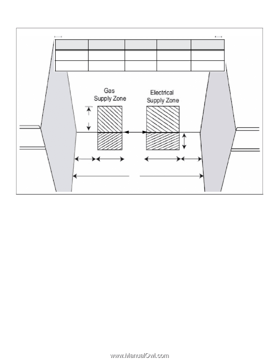
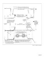
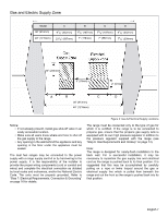
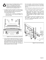
Gas and Electric Supply Zone Model 36" (913mm) 48" (1219mm) A 91/8" (232mm) 231/8" (587mm) B 73/8" (187mm) 7" (178mm) C 73/8" (187mm) 7" (587mm) D 91/8" (232mm) 77/8" (200mm) 10" (254mm) 3" (76mm) 2" (51mm) A B C D 36" (913mm) 48" (1219mm) Notice: • If not already present, install gas shut-off valve in an easily accessible location. • Make sure all users know where and how to shut off the gas supply to the range. • Any opening in the wall behind the appliance and any opening in the floor under the appliance must be sealed. The dual fuel ranges may be connected to the power supply with a range supply cord kit or by hard-wiring to the power supply. It is the responsibility of the installer to provide the proper wiring components (cord or conduit and wires) and complete the electrical connection as dictated by local codes and ordinances, and/or the National Electric Code. The units must be properly grounded. Refer to "Step 7: Electrical Requirements, Connection & Grounding" on page 16 for details. Figure 3: Gas & Electrical Supply Locations The range must be connected only to the type of gas for which it is certified. If the range is to be connected to propane gas, ensure that the propane gas supply tank is equipped with its own high pressure regulator in addition to the pressure regulator supplied with the range (see "Step 6: Gas Requirements and Hookup" on page 14). Note: The range is designed for nearly-flush installation to the back wall. For a successful installation, it may be necessary to reposition the gas supply line and electrical cord as the range is pushed back to its final position. It is suggested that this may be accomplished by carefully pulling on a rope or twine looped around the gas or electrical supply line which is pulled from beneath the range and out the front as the range is pushed back into its final position. English 7
-
 1
1 -
2
-
3
-
 4
4 -
 5
5 -
 6
6 -
 7
7 -
 8
8 -
 9
9 -
 10
10 -
 11
11 -
 12
12 -
 13
13 -
 14
14 -
15
-
16
-
17
-
18
-
19
-
20
-
21
-
22
-
23
-
24
-
25
-
26
-
27
-
28
-
29
-
30
-
31
-
32
-
33
-
34
-
35
-
36
-
37
-
38
-
39
-
40
-
41
-
42
-
43
-
44
-
45
-
46
-
47
-
48
-
49
-
50
-
51
-
52
-
53
-
54
-
55
-
56
-
57
-
58
-
59
-
60
-
61
-
62
-
63
-
64
-
65
-
66
-
67
-
68
-
69
-
70
-
71
-
72
-
73
-
74
-
75
-
76
-
77
-
78
-
79
-
80
-
81
-
82
-
83
-
84
-
85
-
86
-
87
-
88
-
89
-
90
-
91
-
92
-
93
-
94
-
95
-
96
-
97
 |
 |