Thermador PRD486JDGU Installation Manual - Page 17
Warning, Caution - installation manual
 |
View all Thermador PRD486JDGU manuals
Add to My Manuals
Save this manual to your list of manuals |
Page 17 highlights
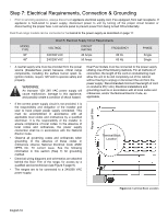
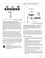
A manual gas shut-off valve must be installed external to the appliance, in a location accessible from the front, for the purpose of shutting off the gas supply. The supply line must not interfere with the back of the unit. The range is supplied with its own pressure regulator that has been permanently mounted inside the range. • Make sure the gas supply is turned off at the manual shut-off valve before connecting the appliance. • Use 3/4" (19mm) flex line to connect between the gas supply and the appliance inlet pipe, which exits the rear, lower right of the appliance. The appliance pipe connection has a 3/4" (19mm) NPT external thread and a 1/2" (13mm) NPT internal thread (see Figure 10 on page 14). • Use caution to avoid crimping the 3/4" (19mm) flex line when making bends. • Suggested length of the flex line is 48" (1219mm); however, check local codes for requirements before installation. • Use pipe sealing compound or Teflon® tape on the pipe threads, and be careful not to apply excessive force when tightening the fittings. Leak testing of the appliance shall be in accordance with the following instructions. • Turn on gas and check supply line connections for leaks using a soap and water solution. • Bubbles forming indicate a gas leak. Repair all leaks immediately after finding them. WARNING: Do not use a flame of any kind to check for gas leaks. Installer is responsible for ensuring that the installation, gas connections, and grounding comply with all applicable codes. CAUTION: The appliance must be isolated from the gas supply piping system by closing its individual manual shut-off valve during any pressure testing of the gas supply piping system at test pressures equal to or less than 1/2 psig (3.5kPa.). The appliance and its individual shut off valve must be disconnected from the gas supply piping system during any pressure testing of the system at test pressures in excess of 1/2 psig (3.5kPa.). When checking the manifold gas pressure, the inlet pressure to the regulator should be at least 6.0" W.C. (14.9 mb) for natural gas or 11.0" W.C. (27.4 mb) for propane. Do not attempt any adjustment of the pressure regulator. English 15
-
 1
1 -
2
-
3
-
4
-
5
-
6
-
7
-
8
-
9
-
10
-
11
-
 12
12 -
 13
13 -
 14
14 -
 15
15 -
 16
16 -
 17
17 -
 18
18 -
 19
19 -
 20
20 -
 21
21 -
 22
22 -
23
-
24
-
25
-
26
-
27
-
28
-
29
-
30
-
31
-
32
-
33
-
34
-
35
-
36
-
37
-
38
-
39
-
40
-
41
-
42
-
43
-
44
-
45
-
46
-
47
-
48
-
49
-
50
-
51
-
52
-
53
-
54
-
55
-
56
-
57
-
58
-
59
-
60
-
61
-
62
-
63
-
64
-
65
-
66
-
67
-
68
-
69
-
70
-
71
-
72
-
73
-
74
-
75
-
76
-
77
-
78
-
79
-
80
-
81
-
82
-
83
-
84
-
85
-
86
-
87
-
88
-
89
-
90
-
91
-
92
-
93
-
94
-
95
-
96
-
97
 |
 |