Toshiba SD5970 Owners Manual - Page 12
Identification, Controls
 |
View all Toshiba SD5970 manuals
Add to My Manuals
Save this manual to your list of manuals |
Page 12 highlights
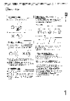
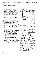
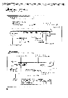
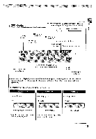
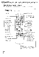
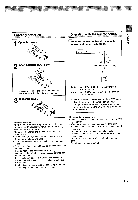
Introduction Identification of Controls D See the page in for details. Front panel ON/STANDBY indicator 1 6> ON: Lit in green Standby mode: Not lit. Disc tray 126> DVD display 13> Remote Sensor 115> PLAY button 126> N ANALOG/HDMI switch 20> SELECT button I 2fil> ON/STANDBY button 26) OPEN/CLOSE button 126) SKIP buttons r31) PAUSE button p> STOP button I 27> Rear panel VIDEO OUT jack I18) VIDEO OUT (Y/Pe/PR) _ (Component video) jacks 119-> OPTICAL DIGITAL AUDIO OUT jack I2≥2 123> I 24> HDMI OUT jack 120> COAXIAL DIGITAL AUDIO OUT jack L22) 23> F24> Power cord ANALOG AUDIO OUT (UR) jacks I19> S VIDEO OUT jack 118> When connecting the optical digital cable, remove the cap and fit the connector into the jack firmly. When not using the jack, keep the cap inserted to protect it from dust intrusion. 12
-
 1
1 -
2
-
3
-
4
-
5
-
6
-
 7
7 -
 8
8 -
 9
9 -
 10
10 -
 11
11 -
 12
12 -
 13
13 -
 14
14 -
 15
15 -
 16
16 -
 17
17 -
18
-
19
-
20
-
21
-
22
-
23
-
24
-
25
-
26
-
27
-
28
-
29
-
30
-
31
-
32
-
33
-
34
-
35
-
36
-
37
-
38
-
39
-
40
-
41
-
42
-
43
-
44
-
45
-
46
-
47
-
48
-
49
-
50
-
51
-
52
-
53
-
54
-
55
-
56
-
57
-
58
-
59
-
60
-
61
-
62
-
63
-
64
-
65
-
66
-
67
-
68
-
69
-
70
-
71
-
72
-
73
-
74
 |
 |
