ViewSonic VP150M Service Manual - Page 9
digital, display, DVI_D, connector, video, input, source., Description
 |
UPC - 766907700619
View all ViewSonic VP150M manuals
Add to My Manuals
Save this manual to your list of manuals |
Page 9 highlights
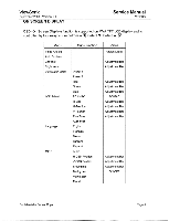
Service Manual VP150m PIN ASSIGNMENT ViewSonic September 2000 - Version 1.0 The MVA TFT LCD digital display uses a 24 Pin DVI_D connector as video input source. Pin Description 1 TMDS negative differential input, channel 2 2 TMDS positive differential input, channel 2 3 Logic Ground 4 Reserved. No connection 5 Reserved. No connection 6 DDC2B Clock 7 DDC2B Data 8 Reserved. No connection 9 TMDS negative differential input, channel 1 10 TMDS positive differential input, channel 1 11 Logic Ground 12 Reserved. No connection 13 Reserved. No connection 14 Power 15 Logic Ground 16 SENSE Pin, Pull High 17 TMDS negative differential input, channel 0 18 TMDS positive differential input, channel 0 19 Logic Ground 20 Reserved. No connection 21 Reserved. No connection 22 Logic Ground 23 TMDS positive differential input, reference clock 24 TMDS negative differential input, reference clock I 0 Page 8 Confidential - Do Not Copy
-
 1
1 -
2
-
3
-
 4
4 -
 5
5 -
 6
6 -
 7
7 -
 8
8 -
 9
9 -
 10
10 -
 11
11 -
 12
12 -
 13
13 -
 14
14 -
15
-
16
-
17
-
18
-
19
-
20
-
21
-
22
-
23
-
24
-
25
-
26
-
27
-
28
-
29
-
30
-
31
-
32
-
33
-
34
-
35
-
36
-
37
-
38
-
39
-
40
-
41
-
42
-
43
-
44
-
45
-
46
-
47
-
48
-
49
-
50
-
51
-
52
-
53
-
54
-
55
-
56
-
57
-
58
-
59
-
60
-
61
-
62
-
63
-
64
-
65
-
66
-
67
-
68
-
69
-
70
-
71
-
72
-
73
-
74
-
75
-
76
-
77
-
78
 |
 |
