Yamaha R-V905 Owner's Manual - Page 14
Connections, Connections With Other Components - owners manual
 |
View all Yamaha R-V905 manuals
Add to My Manuals
Save this manual to your list of manuals |
Page 14 highlights
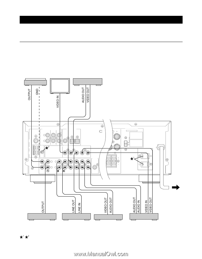
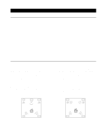
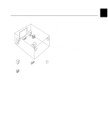
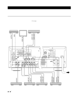
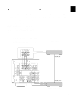
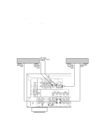
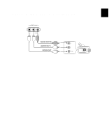
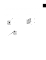
CONNECTIONS Never plug in this unit and other components until all connections are completed. CONNECTIONS WITH OTHER COMPONENTS When making connections between this unit and other components, be sure all connections are made correctly, that is to say L (left) to L, R (right) to R, "+" to "+" and "-" to "-". Also, refer to the owner's manual for each component to be connected to this unit. * If you have YAMAHA components numbered as !, #, $, etc. on the rear panel, connections can be made easily by making sure to connect the output (or input) terminals of each component to the same-numbered terminals of this unit. Turntable Monitor TV DVD player, LD player, etc. 75Ω UNBAL. EXTERNAL DECODER INPUT MAIN CENTER SURROUND L DIGITAL SIGNAL COAXIAL DVD/LD OPTICAL DVD/LD TV/DBS FM ANT GND AM ANT R GND SUB WOOFER VIDEO SIGNAL LL MONITOR OUT DVD/LD AUDIO SIGNAL TV/DBS IN OUT VCR OUTPUT RR PHONO CD IN OUT (PLAY) (REC) TAPE/MD DVD/LD TV/DBS IN OUT VCR SUB WOOFER L REAR R (SORROUND) L (U.S.A. model) IMPEDANCE SELECTOR SET BEFORE POWER ON MAIN A OR B: 4ΩMIN. /SPEAKER A + B: 8ΩMIN. /SPEAKER CENTER: 6ΩMIN. /SPEAKER REAR : 6ΩMIN. /SPEAKER MAIN A OR B: 8ΩMIN. /SPEAKER A + B:I6ΩMIN. /SPEAKER CENTER: 8ΩMIN. /SPEAKER REAR : 8ΩMIN. /SPEAKER AC OUTLETS SWITCHED 100W MAX. TOTAL MAINS UAL FOR CORRECT SETTING. To AC outlet CD player Tape deck, MD recorder, etc. , : See the next page. 14 TV/DBS tuner VCR (Video cassette recorder)
-
 1
1 -
2
-
3
-
4
-
5
-
6
-
7
-
8
-
 9
9 -
 10
10 -
 11
11 -
 12
12 -
 13
13 -
 14
14 -
 15
15 -
 16
16 -
 17
17 -
 18
18 -
 19
19 -
20
-
21
-
22
-
23
-
24
-
25
-
26
-
27
-
28
-
29
-
30
-
31
-
32
-
33
-
34
-
35
-
36
-
37
-
38
-
39
-
40
-
41
-
42
-
43
-
44
-
45
-
46
-
47
-
48
-
49
-
50
-
51
-
52
-
53
-
54
-
55
-
56
-
57
-
58
-
59
-
60
-
61
-
62
-
63
-
64
-
65
-
66
-
67
-
68
-
69
 |
 |