Yamaha V3.0.x M7cl V3 Editor Owner's Manual (v3.0.x) - Page 35
KEY IN SOURCE, KEY IN FILTER, LIBRARY, Response curve, GR meter, THRESHOLD, If COMPRESSOR is selected
 |
View all Yamaha V3.0.x manuals
Add to My Manuals
Save this manual to your list of manuals |
Page 35 highlights
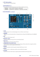
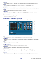
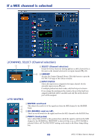
J HOLD Specifies the time that the gate will remain open after the key-in signal falls below the threshold. K KEY IN SOURCE Click this to select one of the following signals to use as the key-in source. SELF PRE EQ SELF POST EQ MIX OUT 13-16 CH 1-48 POST EQ STIN1L-STIN4R POST EQ The pre-EQ signal of the currently selected input channel The post-EQ signal of the currently selected input channel The output signal of the corresponding MIX channel immediately before the output attenuation The post-EQ signal of the corresponding input channel (however, you can only choose channels belonging to the same group, within the seven groups CH1-8, CH9-16, CH17-24, CH25-32, CH33-40, CH41-48, and STIN1L-STIN4R). L CUE This button cue-monitors the currently selected key-in signal. This is not shown in the ADDITIONAL VIEW. M KEY IN FILTER Select the type of filter applied to the selected key-in signal; HPF (high pass filter), BPF (band pass filter), or LPF (low pass filter). The ON/OFF button switches the filter on/off. If you've selected BPF, use the two knobs to adjust the band pass frequency and Q. If you've selected HPF or LPF, use the knob to adjust the cutoff frequency. If COMPRESSOR is selected 51 4 2 3 6 7 8 9 J K L A TYPE Indicates the type of the currently selected compressor. You can click here to select the type. B LIBRARY This button accesses the dynamics library. Clicking this button will open the DYNAMICS page of the LIBRARY window. C ON This button switches the compressor on/off. D Response curve Indicates the response for the compressor of the currently selected channel. E GR meter This meter indicates the amount of gain reduction produced by the compressor. F THRESHOLD Specifies the threshold level at which the compressor will operate. The input signal will start being compressed when the key-in signal exceeds this level; compression will be removed when the signal falls below this level. 35 M7CL V3 Editor Owner's Manual
-
 1
1 -
2
-
3
-
4
-
5
-
6
-
7
-
8
-
9
-
10
-
11
-
12
-
13
-
14
-
15
-
16
-
17
-
18
-
19
-
20
-
21
-
22
-
23
-
24
-
25
-
26
-
27
-
28
-
29
-
 30
30 -
 31
31 -
 32
32 -
 33
33 -
 34
34 -
 35
35 -
 36
36 -
 37
37 -
 38
38 -
 39
39 -
 40
40 -
41
-
42
-
43
-
44
-
45
-
46
-
47
-
48
-
49
-
50
-
51
-
52
-
53
-
54
-
55
-
56
-
57
-
58
-
59
-
60
-
61
-
62
-
63
-
64
-
65
-
66
-
67
-
68
-
69
-
70
-
71
-
72
-
73
-
74
-
75
-
76
-
77
-
78
-
79
-
80
 |
 |
