Yamaha V3.0.x M7cl V3 Editor Owner's Manual (v3.0.x) - Page 39
Recall Safe/mute Safe, Dca Group/mute Group, Fader, Direct Out Port, Mute Group
 |
View all Yamaha V3.0.x manuals
Add to My Manuals
Save this manual to your list of manuals |
Page 39 highlights
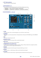
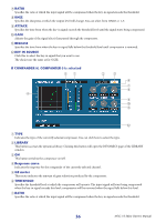
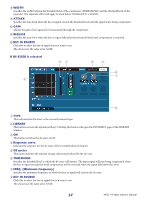
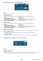
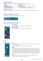
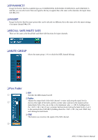
C DIRECT OUT PORT Click this to select one of the following output ports as the one used for direct out. NONE OMNI 1-8 OMNI 9-16(M7CL-32/48) SLOT1-1, SLOT1-2...SLOT3-16 No assignment OMNI OUT jacks 1-8 OMNI OUT jacks 9-16 Output channels of an I/O card installed in slots 1-3 D DIRECT OUT POINT Selects the position at which direct out will be patched. Choose from PRE HPF, PRE EQ, PRE FADER, or POST ON. ❏ RECALL SAFE/MUTE SAFE These enable/disable Recall Safe and Mute Safe for the channel. ❏ DCA GROUP/MUTE GROUP 12 A DCA GROUP Selects the DCA group (1-8) to which that channel belongs. BMUTE GROUP Selects the mute group (1-8) to which that channel belongs. ❏ Fader 1 2 3 A ON Switches the input channel on/off. This is linked with the INPUT section CH [ON] keys on the M7CL's panel. If the corresponding channel is off, the fader will be grayed out. B Fader Adjusts the input level of the input channel. This is linked with the INPUT section faders of the M7CL's panel. A meter indicating the signal level is shown at the right of the fader, and the current value is shown in the numerical box immediately below. You can set this to the minimum value (-∞ dB) by holding down the (< >) key of your computer keyboard and clicking the fader knob, or set it to the nominal value (0.00 dB) by holding down the (< >) key and key and clicking the fader knob. C CUE This button cue-monitors the signal of the input channel. This is linked with the INPUT section [CUE] keys on the M7CL's panel. 39 M7CL V3 Editor Owner's Manual
-
 1
1 -
2
-
3
-
4
-
5
-
6
-
7
-
8
-
9
-
10
-
11
-
12
-
13
-
14
-
15
-
16
-
17
-
18
-
19
-
20
-
21
-
22
-
23
-
24
-
25
-
26
-
27
-
28
-
29
-
30
-
31
-
32
-
33
-
 34
34 -
 35
35 -
 36
36 -
 37
37 -
 38
38 -
 39
39 -
 40
40 -
 41
41 -
 42
42 -
 43
43 -
 44
44 -
45
-
46
-
47
-
48
-
49
-
50
-
51
-
52
-
53
-
54
-
55
-
56
-
57
-
58
-
59
-
60
-
61
-
62
-
63
-
64
-
65
-
66
-
67
-
68
-
69
-
70
-
71
-
72
-
73
-
74
-
75
-
76
-
77
-
78
-
79
-
80
 |
 |
