ZyXEL ES3500-24HP User Guide - Page 96
PoE Setup
 |
View all ZyXEL ES3500-24HP manuals
Add to My Manuals
Save this manual to your list of manuals |
Page 96 highlights
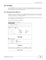
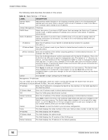
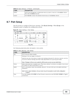
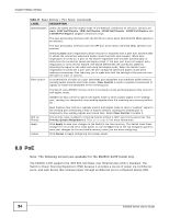
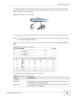
Chapter 8 Basic Setting Table 18 Basic Setting > PoE Status LABEL Consuming Power (W) Allocated Power (W) DESCRIPTION This field displays the total amount of power the Switch is currently supplying to the connected PoE-enabled devices. This field displays the total amount of power the Switch has reserved for PoE after negotiating with the connected PoE device(s). Remaining Power (W) Consuming Power (W) can be less than or equal but not more than the Allocated Power (W). This field displays the amount of power the Switch can still provide for PoE. Port State Note: The Switch must have at least 16 W of remaining power in order to supply power to a PoE device, even if the PoE device needs less than 16 W. This is the port index number. This field shows which ports can receive power from the Switch. You can set this in the Basic Setting > PoE Status screen. Class • Disable - The PD connected to this port cannot get power. • Enable - The PD connected to this port can receive power. This shows the power classification of the PD. This is a number from 0 to 4, where each value represents a range of power (W) and current (mA) that the PD requires to function. The ranges are as follows. PD Priority • Class 0 - Default, 0.44 to 12.94 • Class 1 - Optional, 0.44 to 3.84 • Class 2 - Optional, 3.84 to 6.49 • Class 3 - Optional, 6.49 to 12.95 • Class 4 - Reserved (PSEs classify as Class 0) in a switch that supports IEEE 802.3af only. Optional, 12.95 to 25.50 in a switch that supports IEEE 802.3at. When the total power requested by the PDs exceeds the total PoE power budget on the Switch, you can set the PD priority to allow the Switch to provide power to ports with higher priority first. Consuming Power (mW) Max Power (mW) Max Current (mA) • Critical has the highest priority. • High has the Switch assign power to the port after all critical priority ports are served. • Low has the Switch assign power to the port after all critical and high priority ports are served. This field displays the current amount of power consumed by the PD from the Switch on this port. This field displays the maximum amount of power the PD could use from the Switch on this port. This field displays the maximum amount of current drawn by the PD from the Switch on this port. 8.8.1 PoE Setup Use this screen to set the priority levels for the Switch in distributing power to PDs. 96 ES3500 Series User's Guide
-
 1
1 -
2
-
3
-
4
-
5
-
6
-
7
-
8
-
9
-
10
-
11
-
12
-
13
-
14
-
15
-
16
-
17
-
18
-
19
-
20
-
21
-
22
-
23
-
24
-
25
-
26
-
27
-
28
-
29
-
30
-
31
-
32
-
33
-
34
-
35
-
36
-
37
-
38
-
39
-
40
-
41
-
42
-
43
-
44
-
45
-
46
-
47
-
48
-
49
-
50
-
51
-
52
-
53
-
54
-
55
-
56
-
57
-
58
-
59
-
60
-
61
-
62
-
63
-
64
-
65
-
66
-
67
-
68
-
69
-
70
-
71
-
72
-
73
-
74
-
75
-
76
-
77
-
78
-
79
-
80
-
81
-
82
-
83
-
84
-
85
-
86
-
87
-
88
-
89
-
90
-
 91
91 -
 92
92 -
 93
93 -
 94
94 -
 95
95 -
 96
96 -
 97
97 -
 98
98 -
 99
99 -
 100
100 -
 101
101 -
102
-
103
-
104
-
105
-
106
-
107
-
108
-
109
-
110
-
111
-
112
-
113
-
114
-
115
-
116
-
117
-
118
-
119
-
120
-
121
-
122
-
123
-
124
-
125
-
126
-
127
-
128
-
129
-
130
-
131
-
132
-
133
-
134
-
135
-
136
-
137
-
138
-
139
-
140
-
141
-
142
-
143
-
144
-
145
-
146
-
147
-
148
-
149
-
150
-
151
-
152
-
153
-
154
-
155
-
156
-
157
-
158
-
159
-
160
-
161
-
162
-
163
-
164
-
165
-
166
-
167
-
168
-
169
-
170
-
171
-
172
-
173
-
174
-
175
-
176
-
177
-
178
-
179
-
180
-
181
-
182
-
183
-
184
-
185
-
186
-
187
-
188
-
189
-
190
-
191
-
192
-
193
-
194
-
195
-
196
-
197
-
198
-
199
-
200
-
201
-
202
-
203
-
204
-
205
-
206
-
207
-
208
-
209
-
210
-
211
-
212
-
213
-
214
-
215
-
216
-
217
-
218
-
219
-
220
-
221
-
222
-
223
-
224
-
225
-
226
-
227
-
228
-
229
-
230
-
231
-
232
-
233
-
234
-
235
-
236
-
237
-
238
-
239
-
240
-
241
-
242
-
243
-
244
-
245
-
246
-
247
-
248
-
249
-
250
-
251
-
252
-
253
-
254
-
255
-
256
-
257
-
258
-
259
-
260
-
261
-
262
-
263
-
264
-
265
-
266
-
267
-
268
-
269
-
270
-
271
-
272
-
273
-
274
-
275
-
276
-
277
-
278
-
279
-
280
-
281
-
282
-
283
-
284
-
285
-
286
-
287
-
288
-
289
-
290
-
291
-
292
-
293
-
294
-
295
-
296
-
297
-
298
-
299
-
300
-
301
-
302
-
303
-
304
-
305
-
306
-
307
-
308
-
309
-
310
-
311
-
312
-
313
-
314
-
315
-
316
-
317
-
318
-
319
-
320
-
321
-
322
-
323
-
324
-
325
-
326
-
327
-
328
-
329
-
330
-
331
-
332
-
333
-
334
-
335
-
336
-
337
-
338
-
339
-
340
-
341
-
342
-
343
-
344
-
345
-
346
-
347
-
348
-
349
-
350
-
351
-
352
-
353
-
354
-
355
-
356
-
357
-
358
-
359
-
360
 |
 |
