AMD AXDA3200DKV4E Data Sheet - Page 4

Electrical Data .29, Signal and Power-Up Requirements .43, Mechanical Data.. 47 - frequency

Page 4 highlights

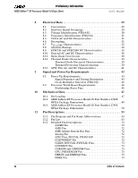
Preliminary Information AMD Athlon™ XP Processor Model 10 Data Sheet 26237C-May 2003 8 Electrical Data 29 8.1 Conventions 29 8.2 Interface Signal Groupings 29 8.3 Voltage Identification (VID[4:0 30 8.4 Frequency Identification (FID[3:0 31 8.5 VCCA AC and DC Characteristics 31 8.6 Decoupling 31 8.7 VCC_CORE Characteristics 32 8.8 Absolute Ratings 34 8.9 SYSCLK and SYSCLK# DC Characteristics 35 8.10 General AC and DC Characteristics 36 8.11 Open Drain Test Circuit 38 8.12 Thermal Diode Characteristics 39 Thermal Diode Electrical Characteristics 39 Thermal Protection Characterization 39 8.13 APIC Pins AC and DC Characteristics 41 9 Signal and Power-Up Requirements 43 9.1 Power-Up Requirements 43 Signal Sequence and Timing Description 43 Clock Multiplier Selection (FID[3:0 46 9.2 Processor Warm Reset Requirements 46 Northbridge Reset Pins 46 10 Mechanical Data 47 10.1 Die Loading 47 10.2 AMD Athlon XP Processor Model 10 Part Number 27488 OPGA Package Dimensions 48 10.3 AMD Athlon XP Processor Model 10 Part Number 27493 OPGA Package Dimensions 50 11 Pin Descriptions 53 11.1 Pin Diagram and Pin Name Abbreviations 53 11.2 Pin List 63 11.3 Detailed Pin Descriptions 72 A20M# Pin 72 AMD Pin 72 AMD Athlon System Bus Pins 72 Analog Pin 72 APIC Pins, PICCLK, PICD[1:0 72 CLKFWDRST Pin 72 CLKIN, RSTCLK (SYSCLK) Pins 73 CONNECT Pin 73 COREFB and COREFB# Pins 73 CPU_PRESENCE# Pin 73 DBRDY and DBREQ# Pins 73 FERR Pin 73 iv Table of Contents

  • 1
  • 2
  • 3
  • 4
  • 5
  • 6
  • 7
  • 8
  • 9
  • 10
  • 11
  • 12
  • 13
  • 14
  • 15
  • 16
  • 17
  • 18
  • 19
  • 20
  • 21
  • 22
  • 23
  • 24
  • 25
  • 26
  • 27
  • 28
  • 29
  • 30
  • 31
  • 32
  • 33
  • 34
  • 35
  • 36
  • 37
  • 38
  • 39
  • 40
  • 41
  • 42
  • 43
  • 44
  • 45
  • 46
  • 47
  • 48
  • 49
  • 50
  • 51
  • 52
  • 53
  • 54
  • 55
  • 56
  • 57
  • 58
  • 59
  • 60
  • 61
  • 62
  • 63
  • 64
  • 65
  • 66
  • 67
  • 68
  • 69
  • 70
  • 71
  • 72
  • 73
  • 74
  • 75
  • 76
  • 77
  • 78
  • 79
  • 80
  • 81
  • 82
  • 83
  • 84
  • 85
  • 86
  • 87
  • 88
  • 89
  • 90
  • 91
  • 92
  • 93
  • 94
  • 95
  • 96
  • 97
  • 98
  • 99
  • 100
  • 101
  • 102
  • 103
  • 104

iv
Table of Contents
AMD Athlon™ XP Processor Model 10 Data Sheet
26237C—May 2003
Preliminary Information
8
Electrical Data . . . . . . . . . . . . . . . . . . . . . . . . . . . . . . . . . . . . . . 29
8.1
Conventions . . . . . . . . . . . . . . . . . . . . . . . . . . . . . . . . . . . . . . . . 29
8.2
Interface Signal Groupings . . . . . . . . . . . . . . . . . . . . . . . . . . .29
8.3
Voltage Identification (VID[4:0]) . . . . . . . . . . . . . . . . . . . . . .30
8.4
Frequency Identification (FID[3:0]) . . . . . . . . . . . . . . . . . . . . 31
8.5
VCCA AC and DC Characteristics . . . . . . . . . . . . . . . . . . . . . . 31
8.6
Decoupling . . . . . . . . . . . . . . . . . . . . . . . . . . . . . . . . . . . . . . . . . 31
8.7
V
CC_CORE
Characteristics . . . . . . . . . . . . . . . . . . . . . . . . . . . . . 32
8.8
Absolute Ratings . . . . . . . . . . . . . . . . . . . . . . . . . . . . . . . . . . . . 34
8.9
SYSCLK and SYSCLK# DC Characteristics . . . . . . . . . . . . . . 35
8.10
General AC and DC Characteristics . . . . . . . . . . . . . . . . . . . . 36
8.11
Open Drain Test Circuit . . . . . . . . . . . . . . . . . . . . . . . . . . . . . . 38
8.12
Thermal Diode Characteristics . . . . . . . . . . . . . . . . . . . . . . . .39
Thermal Diode Electrical Characteristics. . . . . . . . . . . . . 39
Thermal Protection Characterization . . . . . . . . . . . . . . . . 39
8.13
APIC Pins AC and DC Characteristics . . . . . . . . . . . . . . . . . .41
9
Signal and Power-Up Requirements . . . . . . . . . . . . . . . . . . . . 43
9.1
Power-Up Requirements . . . . . . . . . . . . . . . . . . . . . . . . . . . . .43
Signal Sequence and Timing Description . . . . . . . . . . . . . 43
Clock Multiplier Selection (FID[3:0]) . . . . . . . . . . . . . . . . 46
9.2
Processor Warm Reset Requirements. . . . . . . . . . . . . . . . . . . 46
Northbridge Reset Pins. . . . . . . . . . . . . . . . . . . . . . . . . . . . 46
10
Mechanical Data. . . . . . . . . . . . . . . . . . . . . . . . . . . . . . . . . . . . . 47
10.1
Die Loading . . . . . . . . . . . . . . . . . . . . . . . . . . . . . . . . . . . . . . . . 47
10.2
AMD Athlon XP Processor Model 10 Part Number 27488
OPGA Package Dimensions . . . . . . . . . . . . . . . . . . . . . . . . . . . 48
10.3
AMD Athlon XP Processor Model 10 Part Number 27493
OPGA Package Dimensions . . . . . . . . . . . . . . . . . . . . . . . . . . . 50
11
Pin Descriptions . . . . . . . . . . . . . . . . . . . . . . . . . . . . . . . . . . . . . 53
11.1
Pin Diagram and Pin Name Abbreviations. . . . . . . . . . . . . . . 53
11.2
Pin List . . . . . . . . . . . . . . . . . . . . . . . . . . . . . . . . . . . . . . . . . . . . 63
11.3
Detailed Pin Descriptions. . . . . . . . . . . . . . . . . . . . . . . . . . . . . 72
A20M# Pin . . . . . . . . . . . . . . . . . . . . . . . . . . . . . . . . . . . . . . 72
AMD Pin . . . . . . . . . . . . . . . . . . . . . . . . . . . . . . . . . . . . . . . . 72
AMDAthlon System Bus Pins . . . . . . . . . . . . . . . . . . . . . .72
Analog Pin . . . . . . . . . . . . . . . . . . . . . . . . . . . . . . . . . . . . . . 72
APIC Pins, PICCLK, PICD[1:0]# . . . . . . . . . . . . . . . . . . . .72
CLKFWDRST Pin . . . . . . . . . . . . . . . . . . . . . . . . . . . . . . . .72
CLKIN, RSTCLK (SYSCLK) Pins. . . . . . . . . . . . . . . . . . . . 73
CONNECT Pin . . . . . . . . . . . . . . . . . . . . . . . . . . . . . . . . . . . 73
COREFB and COREFB# Pins . . . . . . . . . . . . . . . . . . . . . . . 73
CPU_PRESENCE# Pin . . . . . . . . . . . . . . . . . . . . . . . . . . . . 73
DBRDY and DBREQ# Pins . . . . . . . . . . . . . . . . . . . . . . . . . 73
FERR Pin . . . . . . . . . . . . . . . . . . . . . . . . . . . . . . . . . . . . . . . 73