AMD AXDA3200DKV4E Data Sheet - Page 43

Frequency Identification (FID[3:0]), 8.5 VCCA AC and DC Characteristics, 8.6 Decoupling, - - athlon xp 2 2 ghz
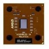
Page 43 highlights

26237C-May 2003 Preliminary Information AMD Athlon™ XP Processor Model 10 Data Sheet 8.4 Frequency Identification (FID[3:0]) Table 11 shows the FID[3:0] DC characteristics. For more information, see "FID[3:0] Pins" on page 74. Table 11. FID[3:0] DC Characteristics Parameter Description Min Max IOL Output Current Low 6 mA VOH Output High Voltage 2.625 V 1 - | VOH - VCC_CORE | ≤ 1.60 V 2 Note: 1. The FID pins must not be pulled above 2.625 V, which is equal to 2.5 V plus a maximum of five percent. 2. Refer to "VCC_2.5V Generation Circuit" found in the section, "Motherboard Required Circuits," of the AMD Athlon™ ProcessorBased Motherboard Design Guide, order# 24363. 8.5 VCCA AC and DC Characteristics Table 12 shows the AC and DC characteristics for VCCA. For more information, see "VCCA Pin" on page 77 Table 12. VCCA AC and DC Characteristics Symbol Parameter Min Nominal Max Units Notes VVCCA VCCA Pin Voltage 2.25 2.5 2.75 | VVCCA - VCC_CORE | ≤ 1.60 V V 1 - 2 IVCCA VCCA Pin Current 0 50 mA/GHz 3 Notes: 1. Minimum and Maximum voltages are absolute. No transients below minimum nor above maximum voltages are permitted. 2. For more information, refer to the AMD Athlon™ Processor-Based Motherboard Design Guide, order# 24363. 3. Measured at 2.5 V. 8.6 Decoupling See the AMD Athlon™ Processor-Based Motherboard Design Guide, order# 24363, or contact your local AMD office for information about the decoupling required on the motherboard for use with the AMD Athlon XP processor model 10. Chapter 8 Electrical Data 31

  • 1
  • 2
  • 3
  • 4
  • 5
  • 6
  • 7
  • 8
  • 9
  • 10
  • 11
  • 12
  • 13
  • 14
  • 15
  • 16
  • 17
  • 18
  • 19
  • 20
  • 21
  • 22
  • 23
  • 24
  • 25
  • 26
  • 27
  • 28
  • 29
  • 30
  • 31
  • 32
  • 33
  • 34
  • 35
  • 36
  • 37
  • 38
  • 39
  • 40
  • 41
  • 42
  • 43
  • 44
  • 45
  • 46
  • 47
  • 48
  • 49
  • 50
  • 51
  • 52
  • 53
  • 54
  • 55
  • 56
  • 57
  • 58
  • 59
  • 60
  • 61
  • 62
  • 63
  • 64
  • 65
  • 66
  • 67
  • 68
  • 69
  • 70
  • 71
  • 72
  • 73
  • 74
  • 75
  • 76
  • 77
  • 78
  • 79
  • 80
  • 81
  • 82
  • 83
  • 84
  • 85
  • 86
  • 87
  • 88
  • 89
  • 90
  • 91
  • 92
  • 93
  • 94
  • 95
  • 96
  • 97
  • 98
  • 99
  • 100
  • 101
  • 102
  • 103
  • 104

Chapter 8
Electrical Data
31
26237C—May 2003
AMD Athlon™ XP Processor Model 10 Data Sheet
Preliminary Information
8.4
Frequency Identification (FID[3:0])
Table 11 shows the FID[3:0] DC characteristics. For more
information, see “FID[3:0] Pins” on page 74.
8.5
VCCA AC and DC Characteristics
Table 12 shows the AC and DC characteristics for VCCA. For more information, see
“VCCA Pin” on page 77
8.6
Decoupling
See the
AMD Athlon™ Processor-Based Motherboard Design
Guide
, order# 24363, or contact your local AMD office for
information about the decoupling required on the motherboard
for use with the AMD Athlon XP processor model 10.
Table 11.
FID[3:0] DC Characteristics
Parameter
Description
Min
Max
I
OL
Output Current Low
6 mA
V
OH
Output High Voltage
2.625 V
1
| V
OH
– V
CC_CORE
|
1.60 V
2
Note:
1.
The FID pins must not be pulled above 2.625 V, which is equal to 2.5 V plus a maximum of five percent.
2.
Refer to “VCC_2.5V Generation Circuit” found in the section, “Motherboard Required Circuits,” of the
AMD Athlon™ Processor-
Based Motherboard Design Guide,
order# 24363.
Table 12.
VCCA AC and DC Characteristics
Symbol
Parameter
Min
Nominal
Max
Units
Notes
V
VCCA
VCCA Pin Voltage
2.25
2.5
2.75
V
1
| V
VCCA
– V
CC_CORE
|
1.60 V
2
I
VCCA
VCCA Pin Current
0
50
mA/GHz
3
Notes:
1.
Minimum and Maximum voltages are absolute. No transients below minimum nor above maximum voltages are permitted.
2.
For more information, refer to the
AMD Athlon™ Processor-Based Motherboard Design Guide,
order# 24363.
3.
Measured at 2.5 V.