Acer EL1210 Service Guide
Acer EL1210 - eMachines - 3 GB RAM Manual
 |
View all Acer EL1210 manuals
Add to My Manuals
Save this manual to your list of manuals |
Acer EL1210 manual content summary:
- Acer EL1210 | Service Guide - Page 1
eMachines EL1210 Service Guide Service guide files and updates are available on the ACER/CSD web; for more information, please refer to http://csd.acer.com.tw PRINTED IN TAIWAN - Acer EL1210 | Service Guide - Page 2
Revision History Please refer to the table below for the updates made on EL1210 service guide. Date Chapter Updates ii - Acer EL1210 | Service Guide - Page 3
Copyright Copyright © 2008 by Acer Incorporated. All rights reserved. No part of this publication may be reproduced, transmitted, computer language, in any form or by any means, electronic, mechanical, magnetic, optical, chemical, manual or otherwise, without the prior written permission of - Acer EL1210 | Service Guide - Page 4
Disclaimer The information in this guide is subject to change without notice. Acer Incorporated makes no representations or warranties purchase, the buyer (and not Acer Incorporated, its distributor, or its dealer) assumes the entire cost of all necessary servicing, repair, and any incidental or - Acer EL1210 | Service Guide - Page 5
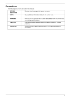
Conventions The following conventions are used in this manual: SCREEN MESSAGES Denotes actual messages that appear on screen. NOTE . Gives precautionary measures to avoid possible hardware or software problems. Reminds you to do specific actions relevant to the accomplishment of procedures. v - Acer EL1210 | Service Guide - Page 6
, your regional office MAY have decided to extend the functionality of a machine (e.g. add-on card, modem, or extra memory capability). These LOCALIZED FEATURES will NOT be covered in this generic service guide. In such cases, please contact your regional offices or the responsible personnel - Acer EL1210 | Service Guide - Page 7
the Optical Drive 36 Removing the Hard Disk Drive 38 Removing the Power Supply 41 Removing the Memory Modules 44 Removing the PCI Card 45 Removing the Front I/O and Card Reader Boards 47 Removing the Mainboard 51 System Troubleshooting 53 Hardware Diagnostic Procedure 53 System - Acer EL1210 | Service Guide - Page 8
viii - Acer EL1210 | Service Guide - Page 9
subsystem Supports up to two DDR2-400/533/667/800/1066 MHz UNB modules Media storage DVD-ROM SATA drive Super-Multi SATA DVD drive 160 or 320 GB SATA hard disk drive Serial ATA controller Embedded SATA controllers Two SATA ports eSATA port (optional) Networking One Gigabit Ethernet - Acer EL1210 | Service Guide - Page 10
) Genuine Windows Vista Home Premium (32/64-bit) Applications Acer Empowering Technology (Acer eRecovery Management) Acer Arcade Live McAfee Internet Security Suite 2008 Trial version Adobe Reader eSobi NTI MediaMaker Power supply 220-watts (115/230 Vac) power supply 2 Chapter 1 - Acer EL1210 | Service Guide - Page 11
is a virtual tour of the EL1210 system's interior and exterior components. Front Panel No. Icon Component 1 Power button/power indicator 2 Optical drive bay door 3 Drive bay door eject button Press to open drive bay door and access the optical drive. 4 Media card reader 5 CF I/II - Acer EL1210 | Service Guide - Page 12
Icon 1 2 3 4 5 6 7 8 9 10 11 12 13 14 15 16 Component Expansion slot (Photo shows graphics card and network/modem card) Headphone/analog speakers jack or front speakers jack Microphone jack USB 2.0 ports CRT/LCD monitor port PS2 keyboard port Voltage selector switch Power connector PS2 mouse - Acer EL1210 | Service Guide - Page 13
Internal Components No. Component 1 Expansion card 2 Mainboard 3 Heat sink fan assembly 4 Power supply 5 Optical drive Chapter 1 5 - Acer EL1210 | Service Guide - Page 14
On Blinking Off On On Off On Blinking Off Description The system has AC power and is powered on. The system is in standby mode. System is not powered on. GbE link network access 100 Mbps link network access 10 Mbps link network access Active network link Ongoing network data activity Off-line - Acer EL1210 | Service Guide - Page 15
BIOS setup loads the configuration values in a battery-backed nonvolatile memory called CMOS RAM. This memory area is not part of the system RAM which allows configuration data to be retained when power "Setup utility" in this guide. The screenshots used in this guide display default system values. - Acer EL1210 | Service Guide - Page 16
, the previous screen displays. When you are making selections from a pop-up menu, closes the pop-up without making a selection. F1 - Display the BIOS setup General Help panel. F5 - Press to load previous default system values. F6 - Press to load fail-safe default system values. F7 - Press - Acer EL1210 | Service Guide - Page 17
Setup Main menu includes the following main setup categories. Product Information Standard CMOS Features Advanced BIOS Features Advanced Chipset Features Integrated Peripherals Power Management Setup PC Health Status Load Default Settings Set Supervisor Password Set User Password - Acer EL1210 | Service Guide - Page 18
the system. These entries are for your reference only and are not user-configurable. Parameter System Manufacturer Product Name System S/N System BIOS Version BIOS Release Date Asset Tag Number Description Name of the manufacturer of this system. Product name of the system. Serial number of the - Acer EL1210 | Service Guide - Page 19
Parameter Date Time SATA 1/2 Halt On DIMM1 DIMM2 Total Memory Description Option Set the date following the weekday-month-day Keyboard No Errors All Errors All, But Diskette All, But Disk/Key Also called conventional memory. Typically, 640 KB will be reserved for the MS-DOS OS. Total size - Acer EL1210 | Service Guide - Page 20
Extended IDE Drive Access Mode Description Option Press Enter to view detailed device information connected to the SATA 1/2 connectors When set to Auto, BIOS automatically detect IDE/SATA devices during the POST. Set this parameter to None when there are no IDE/SATA devices used. Auto None - Acer EL1210 | Service Guide - Page 21
Advanced BIOS Features Parameter CPU Feature Hard Disk Boot Priority CD-ROM Boot Priority Virus Warning Quick Power On Self Test First/Second/Third/Fourth Boot Device Boot Up NumLock Status Security Option Full Screen Logo Show Reset Configuration Data Description Press Enter - Acer EL1210 | Service Guide - Page 22
the AMD Virtualization Technology (VT) function. VT allows a single platform to run multiple operating systems in independent partitions. Option Enabled Disabled Hard Disk Boot Priority The Hard Disk Boot Priority submenu allows you to specify the sequence of loading the OS from the installed hard - Acer EL1210 | Service Guide - Page 23
CD-ROM Boot Priority The CD-ROM Boot Priority submenu allows you to specify the sequence of loading the OS from a CD-ROM. If more than one optical drive, use the up or down arrow key to select a hard drive, then press the key or the key to move it up or down on the list. Chapter 2 15 - Acer EL1210 | Service Guide - Page 24
Clock System BIOS cacheable 16 Description This parameter can be configured if the iGPU Frame Buffer Control is set to Manual. Enables or monitor display from the installed PCI Express graphics card or the onboard VGA. Press Enter to configure memory timing and operation settings. Allows you to - Acer EL1210 | Service Guide - Page 25
power down Memclock tri-stating Memory Hole Remapping Auto Optimize Bottom IO Bottom of UMA DRAM [31:24] [FC] Description When set to auto mode, the system reads the electronic data sheet of the memory modules and adjusts the timings accordingly. When set to MaxMemClk, you can manually specify - Acer EL1210 | Service Guide - Page 26
Peripherals Parameter Onboard HD Audio Onboard LAN USB Device Setting Description Enables or disables the onboard audio controller. Enables or disables the built-in network interface card. Press Enter to access the USB Device Setting submenu. Option Auto Disabled Auto Disabled 18 Chapter 2 - Acer EL1210 | Service Guide - Page 27
the onboard USB controller. Select a USB device operation speed. Enables or disables legacy support of the USB keyboard. Enables or disables legacy support of the USB mouse. Enables or disables legacy support of the USB storage device. Option Enabled Disabled Enabled Disabled High Speed Full Low - Acer EL1210 | Service Guide - Page 28
manner when the monitor goes blank. Set a time when the hard disk drives will power down after a period inactivity. Enables or disables the HDD power down function in suspend mode. Set the system to automatically start itself up after a power failure. Enables or disables to wake up the system from - Acer EL1210 | Service Guide - Page 29
PC Health Status Parameter Smart FAN Control Shutdown Temperature Description Enables or disables the smart system fan control function. Set the CPU shutdown temperature. Option Enabled Disabled 90 C/194 F 95 C/203 F 100 C/212 F Disabled Chapter 2 21 - Acer EL1210 | Service Guide - Page 30
Settings The Load Default Settings menu allows you to load the default settings for all BIOS setup parameters. Setup defaults are quite demanding in terms of resources consumption. If you are using low-speed memory chips or other kinds of low-performance components and you choose to load these - Acer EL1210 | Service Guide - Page 31
Set Supervisor Password The Set Supervisor Password menu allows you to set a supervisor password. The supervisor password allows you to access and change all settings in the Setup Utility. Setting a supervisor password 1. Use the up/down arrow keys to select Set Supervisor Password menu then press - Acer EL1210 | Service Guide - Page 32
Set User Password The Set User Password menu allows you to set a user password. Entering this password will restrict a user's access to the Setup menus. A supervisor password must be set first before you can enable or disable this field. A user can only access and modify the system time, system date - Acer EL1210 | Service Guide - Page 33
Save & Exit Setup The Save & Exit Setup menu allows you to save changes made and close the Setup Utility. Chapter 2 25 - Acer EL1210 | Service Guide - Page 34
Exit Without Saving The Exit Without Saving menu allows you to discard changes made and close the Setup Utility. 26 Chapter 2 - Acer EL1210 | Service Guide - Page 35
System Disassembly Chapter 3 This chapter contains step-by-step procedures on how to disassemble the desktop computer for maintenance and troubleshooting. Disassembly Requirements To disassemble the computer, you need the following tools: Wrist grounding strap and conductive mat for preventing - Acer EL1210 | Service Guide - Page 36
procedure, perform the steps listed below: 1. Turn off the system and all the peripherals connected to it. 2. Unplug the power cord from the power outlets. 3. Unplug the power cord from the system. 4. Unplug all peripheral cables from the system. 5. Place the system unit on a flat, stable surface - Acer EL1210 | Service Guide - Page 37
BEZEL HEAT SINK FAN ASSEMBLY CPU Bx1 OPTICAL DISK DRIVE Cx1 HDD-ODD BRACKET Ax3 Cx1 POWER SUPPLY Dx4 HDD MODULE HDD MEMORY MODULES Ex1 PCI CARD Dx2 FRONT I/O AND CARD READER BOARD BRACKET Cx6 MAINBOARD Cx2 FRONT I/O BOARD Cx2 CARD READER BOARD Screw List A B C D E Chapter 3 Screw #6-32 L5 - Acer EL1210 | Service Guide - Page 38
Removing the Side Panel 1. Perform the pre-disassembly procedure described on page 28. 2. Remove the two screws (A) located on the rear edge of the side panel. Screw (Quantity) #6-32 L5 BZN (2) Color Black Torque 5.5 to 6.5 kgf-cm Part No. 86.00J07.B60 3. Slide the side panel toward the back of - Acer EL1210 | Service Guide - Page 39
Removing the Front Bezel 1. Remove the side panel. Refer to the previous section for instructions. 2. Release the front bezel retention tabs from the chassis interior. 3. Pull the bezel away from the chassis. Chapter 3 31 - Acer EL1210 | Service Guide - Page 40
Removing the Heat Sink Fan Assembly WARNING:The heat sink becomes very hot when the system is on. NEVER touch the heat sink with any metal or with your hands. 1. See "Removing the Side Panel" on page 30. 2. See "Removing the Front Bezel" on page 31. 3. Use a long-nosed screwdriver to loosen the four - Acer EL1210 | Service Guide - Page 41
5. Lay down the heat sink fan assembly, in an upright position, on top of the optical drive, as shown below, then disconnect the fan cable from the mainboard. 6. Remove the heat sink fan assembly from the chassis then lay it down in an upright position-with the thermal patch facing upward. Do not - Acer EL1210 | Service Guide - Page 42
Removing the Processor IMPORTANT:Before removing a processor from the mainboard, make sure to create a backup file of all important data. WARNING:The processor becomes very hot when the system is on. Allow it to cool off first before handling. 1. See "Removing the Side Panel" on page 30. 2. See " - Acer EL1210 | Service Guide - Page 43
IMPORTANT:If you are going to install a new processor, note the arrow on the corner to make sure the processor is properly oriented over the socket. Chapter 3 35 - Acer EL1210 | Service Guide - Page 44
" on page 31. 3. See "Removing the Heat Sink Fan Assembly" on page 32. 4. See "Removing the Processor" on page 34. 5. Disconnect the data and power cables from the rear of the optical drive and the mainboard. 6. Remove the screw (B) from the optical drive. Screw (Quantity) M3xL5 (1) 36 Color Black - Acer EL1210 | Service Guide - Page 45
7. Pull the drive out of the drive bay. Chapter 3 37 - Acer EL1210 | Service Guide - Page 46
Removing the Hard Disk Drive 1. See "Removing the Side Panel" on page 30. 2. See "Removing the Front Bezel" on page 31. 3. See "Removing the Heat Sink Fan Assembly" on - Acer EL1210 | Service Guide - Page 47
b. Lift the bracket up and turn it over. 7. Disconnect the data and power cables from the rear of the hard drive. 8. Place the bracket on a clean, static-free work surface. Chapter 3 39 - Acer EL1210 | Service Guide - Page 48
9. Remove the HDD module. a. Remove the four screws (D) that secure the HDD module to the HDD bracket. Screw (Quantity) #6-32*3/16 NI (4) Color Silver b. Slide the HDD out of the bracket. Torque 5.5 to 6.5 kgf-cm Part No. 86.5A5B6.012 40 Chapter 3 - Acer EL1210 | Service Guide - Page 49
Sink Fan Assembly" on page 32. 4. See "Removing the Processor" on page 34. 5. See "Removing the Optical Drive" on page 36. 6. See "Removing the Hard Disk Drive" on page 38. 7. Disconnect the 4-pin and 24-pin power supply cables from the mainboard. Chapter 3 41 - Acer EL1210 | Service Guide - Page 50
chassis. Screw (Quantity) #6-32 L6 BZN (1) Color Silver Torque 5.5 to 6.5 kgf-cm Part No. 86.00J44.C60 9. Remove the three screws (A) that secure the power supply to the rear panel. Screw (Quantity) #6-32 L5 BZN (3) Color Black Torque 5.5 to 6.5 kgf-cm Part No. 86.00J07.B60 42 Chapter 3 - Acer EL1210 | Service Guide - Page 51
10. Lift the power supply module out of the chassis. Chapter 3 43 - Acer EL1210 | Service Guide - Page 52
IMPORTANT:Before removing any DIMM from the memory board, make sure to create a backup file of all important " on page 34. 5. See "Removing the Optical Drive" on page 36. 6. See "Removing the Hard Disk Drive" on page 38. 7. Press the holding clips on both sides of the DIMM slot outward to release - Acer EL1210 | Service Guide - Page 53
See "Removing the Processor" on page 34. 5. See "Removing the Optical Drive" on page 36. 6. See "Removing the Hard Disk Drive" on page 38. 7. Remove the screw (E) that secures the card to the chassis. Screw (Quantity) #6-32 5MM NI (1) Color Silver Torque 5.5 to 6.5 kgf-cm Part No. 86.9A5G6.162 - Acer EL1210 | Service Guide - Page 54
8. Gently pull the card to remove it from the mainboard. 46 Chapter 3 - Acer EL1210 | Service Guide - Page 55
See "Removing the Optical Drive" on page 36. 6. See "Removing the Hard Disk Drive" on page 38. 7. See "Removing the Memory Modules" on page 44. 8. Disconnect one end of the USB and audio cables from the front I/O and card reader boards. 9. Open the cable retention clip, then disconnect the USB and - Acer EL1210 | Service Guide - Page 56
a. Remove the two screws (D) that secure the bracket to the chassis. Screw (Quantity) #6-32*3/16 NI (2) Color Silver Torque 5.5 to 6.5 kgf-cm b. Push the bracket into the chassis then remove the bracket. Part No. 86.5A5B6.012 11. Remove the card reader board. 48 Chapter 3 - Acer EL1210 | Service Guide - Page 57
reader board to the bracket. Screw (Quantity) #6-32 L6 NI (2) Color Black Torque 5.5 to 6.5 kgf-cm b. Pull the card reader board out of the bracket. Part No. 86.00J44.C60 12. Remove the front I/O board. a. Remove the two screws (C) that secure the I/O board to - Acer EL1210 | Service Guide - Page 58
b. Pull the I/O board out of the bracket. 50 Chapter 3 - Acer EL1210 | Service Guide - Page 59
34. 5. See "Removing the Optical Drive" on page 36. 6. See "Removing the Hard Disk Drive" on page 38. 7. See "Removing the Memory Modules" on page 44. 8. See "Removing the PCI Card" on page 45. 9. See "Removing the Front I/O and Card Reader Boards" on page 47. 10. Disconnect the LED cable from the - Acer EL1210 | Service Guide - Page 60
11. Remove the six screws (C) that secure the mainboard to the chassis, in the order shown. Screw (Quantity) #6-32 L5 BZN (6) Color Silver 12. Lift the board from the chassis. Torque 5.5 to 6.5 kgf-cm Part No. 86.00J44.C60 52 Chapter 3 - Acer EL1210 | Service Guide - Page 61
Chapter 4 This chapter provides instructions on how to troubleshoot system hardware problems. Hardware Diagnostic Procedure IMPORTANT:The diagnostic tests described in this chapter are only intended to test Acer products. Non-Acer products, prototype cards, or modified options can give - Acer EL1210 | Service Guide - Page 62
their appropriate connectors. 9. Verify that all components are Acer-qualified and supported. 10. Replace the system covers. 11. Power on the system. 12. If the problem with the system is not evident, you can try viewing the POST messages and BIOS event logs during the system startup. 54 Chapter 4 - Acer EL1210 | Service Guide - Page 63
after the video card has been activated. Not all computers using AMIBIOS enable this feature. In most cases, a checkpoint card is the System is ready. System is OK. Memory not installed or memory error. VGA not installed or VGA error. BIOS damaged. CMOS damaged. CMOS checksum error. Chapter - Acer EL1210 | Service Guide - Page 64
memory installed. Others may indicate a problem with a device, such as the way it has been configured. NOTE: If the system fails after you make changes in the BIOS shadow RAM Disable L2 cache (socket 7 or below) Program basic chipset registers Detect memory Auto support. Reserved 56 Chapter 4 - Acer EL1210 | Service Guide - Page 65
Also set realtime clock power status, and then check settings into BIOS stack. If CMOS checksum fails, use default value instead. Prepare BIOS resource map for memory & I/O resource Search for a valid VGA device & VGA BIOS 09 buffer Reserved 1 Program CPU internal MTRR (P6 & PII) for 0-640K memory - Acer EL1210 | Service Guide - Page 66
Test 8259 interrupt mask bits for channel 2 Reserved Reserved Test 8259 functionality Reserved Reserved Reserved Initialize EISA slot Reserved 1 Calculate total memory by testing the last double word of each 64K page. 2 Program write allocation for AMD K5 CPU. Reserved Reserved Reserved Reserved - Acer EL1210 | Service Guide - Page 67
67h 68h 69h 6Ah 6Bh 6Ch 6Dh 6Eh 6Fh 70h 71h 72h 73h 74h 75h POST Routine Description Reserved Test all memory (clear all extended memory to 0) Clear password according to H/W jumper (Optional) Reserved Display number of processors (multi-processor platform) Reserved 1 Display PnP logo 2 Early ISA - Acer EL1210 | Service Guide - Page 68
to text mode if full screen logo is supported. If errors occur, report errors & Clear EPA or customization logo Reserved Reserved 1 Call chipset power management hook 2 Recover the text fond used by EPA logo 2 Set up ACPI table at top of the memory Reserved 1 Invoke all ISA adapter ROMs 2 Invoke - Acer EL1210 | Service Guide - Page 69
95h 96h FFh POST Routine Description 1 Enable L2 cache 2 Program Daylight Saving 3 Program boot up speed 4 Chipset final initialization 5 Power management final initialization 6 Clear screen & display summary table 7 Program K6 write allocation 8 Program P6 class write combining Update keyboard LED - Acer EL1210 | Service Guide - Page 70
whenever you need them. In the Support & Downloads tab you can download information materials for all of Acer notebook, desktop and server models including: Service guides for all models User's manuals Training materials BIOS updates Software utilities Spare parts lists Technical - Acer EL1210 | Service Guide - Page 71
Chapter 5 System Block Diagram and Board Layout System Block Diagram Chapter 5 63 - Acer EL1210 | Service Guide - Page 72
1 Top: PS2 Mouse Port 11 USBF2 Bottom: PS2 Keyboard Port 2 PWR1 4-pin ATX power connector 12 USBF1 3 Processor socket 13 JBIOS1 4 CPUFAN1 Processor fan cable connector 14 SATA1 5 PWR2 24-pin ATX power connector 15 PCIEX1 6 DIMM1 and 2 System memory slots 16 AUDIOF1 7 DEBUGH1 Debug - Acer EL1210 | Service Guide - Page 73
System Jumpers Name Clear CMOS/NVRAM Location JBIOS1 Default 1-2 2-3 Settings Normal (default) Clear CMOS Chapter 5 65 - Acer EL1210 | Service Guide - Page 74
66 Chapter 5 - Acer EL1210 | Service Guide - Page 75
FRU (Field Replaceable Unit) list in global configuration of the EL1210 desktop computer. Refer to this chapter whenever ordering the parts to repair , it will NOT be noted on the printed Service Guide. For Acer authorized service providers, your Acer office may have a different part number code from - Acer EL1210 | Service Guide - Page 76
EL1210 Exploded Diagram NOTE: This section will be updated as more information becomes available. 68 Chapter 6 - Acer EL1210 | Service Guide - Page 77
EL1210 FRU List (81.3V801.007G) Component Board Front I/O board QTY Part Name 1 FRONT I/O BOARD Card reader board 1 CARD READER BOARD Modem card 1 MODEM CARD with 1 CHASSIS WITH POWER & LED power and LED CABLE & HDD Acer Part Number DA078L/BOXER FRONT I/O BD MRP DA061L/BOXER61 CARD - Acer EL1210 | Service Guide - Page 78
Sempron, 45W Optical drive DVD-RW drive DVD-ROM drive Hard disk drive 160 GB 320 GB Heat sink QTY Part Name Description 1 - G2 1300 1 CPU AMD 1.9G SDH1100IAA3DE IC CPU SEMPRON LE-1100 1.9G SEMPRON LE-1100 Acer Part Number KC.ALE02.164 KC.ALE02.166 KC.ALF02.160 KC.ALF02.162 KC.SLE02.125 KC - Acer EL1210 | Service Guide - Page 79
Component Keyboard Mainboard Memory Mouse Power supply QTY Part Name Description Acer Part Number 1 KEYBOARD PS2 104KEY PRIMAX KB PS2 29-10501G111 US (104) E KB.PS20E.002 29-10501G111 BLACK US 1 KEYBOARD PS2 104KEY CHICONY KB-07053US1976V - Acer EL1210 | Service Guide - Page 80
#6-32 L6 NI BOXER WZS SCRW PAN M3 L5 BZN SCREW FLAT #6-32*3/16 NI PCI e x1 (OR DUMMY BKT)(1) PCI e x16(OR DUMMY BKT)(1) Acer Part Number 86.00J07.B60 86.00J44.C60 86.1A324.5R0 86.5A5B6.012 86.9A5G6.162 72 Chapter 6 - Acer EL1210 | Service Guide - Page 81
Technical Specifications This section provides technical specifications for the system. Processor AMD Athlon Processor Item Type Model number Frequency (MHz) L2 cache size (KB) Socket type Stepping Manufacturing tech (CMOS) Wattage (W) System bus (MHz) Specification AMD Athlon LE-1600 2200 1024 - Acer EL1210 | Service Guide - Page 82
2200 512 AM2 G2 65 nm SOI 45 1600 LE-1300 2500 512 AM2 G2 65 nm SOI 45 - Item System core logic Storage controller Video controller PCI controller LAN controller Specification NVIDIA NForce MCP78 692 BGA NVIDIA NForce MCP78 692 BGA NVIDIA NForce MCP78 692 BGA NVIDIA NForce MCP78 692 - Acer EL1210 | Service Guide - Page 83
vendor BIOS version PCI Interface Item PCI Express controller Number of slots Network Interface Specification Pheonix DAE1LE06 Specification NVIDIA NForce MCP78 692 BGA One PCI Express x 1 slot Item LAN controller Supports LAN protocol LAN connector type Specification NVIDIA NForce MCP78 692 BGA - Acer EL1210 | Service Guide - Page 84
Super Multi DVD-R: 20x max. DVD +R: 20x max. DVD-RW: 6x max. DVD +RW: 8x max. DVD-R DL: 12x max. DVD +R9: 8x max. DVD-RAM: 12x max. CD-R: 48x max. CD-RW: 32x max. DVD: 16x max. CD: 48x max. - DVD: 160 ms CD: 140 ms 2 MB Serial ATA 76 - Acer EL1210 | Service Guide - Page 85
100 ms (Full) CD 140 ms (Full) DVD 160 ms 198KB with buffer under run prevention technology Serial ATA PLDS DH-16D2S DVD-ROM - CD-RAm 5x CD Max 48x DVD Max 16x - CD 12 ms DVD 140 ms DVD - Acer EL1210 | Service Guide - Page 86
Appendix A 78
-
 1
1 -
 2
2 -
 3
3 -
 4
4 -
 5
5 -
 6
6 -
 7
7 -
8
-
9
-
10
-
11
-
12
-
13
-
14
-
15
-
16
-
17
-
18
-
19
-
20
-
21
-
22
-
23
-
24
-
25
-
26
-
27
-
28
-
29
-
30
-
31
-
32
-
33
-
34
-
35
-
36
-
37
-
38
-
39
-
40
-
41
-
42
-
43
-
44
-
45
-
46
-
47
-
48
-
49
-
50
-
51
-
52
-
53
-
54
-
55
-
56
-
57
-
58
-
59
-
60
-
61
-
62
-
63
-
64
-
65
-
66
-
67
-
68
-
69
-
70
-
71
-
72
-
73
-
74
-
75
-
76
-
77
-
78
-
79
-
80
-
81
-
82
-
83
-
84
-
85
-
86
 |
 |

eMachines
EL12
1
0
Service Guide
PRINTED IN TAIWAN
Service guide files and updates are available
on the ACER/CSD web; for more information,
please refer to