Acer EL1210 Service Guide - Page 44
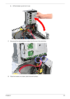
Removing the Optical Drive
 |
View all Acer EL1210 manuals
Add to My Manuals
Save this manual to your list of manuals |
Page 44 highlights
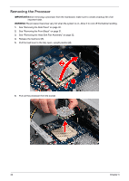
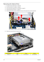
Removing the Optical Drive 1. See "Removing the Side Panel" on page 30. 2. See "Removing the Front Bezel" on page 31. 3. See "Removing the Heat Sink Fan Assembly" on page 32. 4. See "Removing the Processor" on page 34. 5. Disconnect the data and power cables from the rear of the optical drive and the mainboard. 6. Remove the screw (B) from the optical drive. Screw (Quantity) M3xL5 (1) 36 Color Black Torque 5.5 to 6.5 kgf-cm Part No. 86.1A324.5R0 Chapter 3
-
 1
1 -
2
-
3
-
4
-
5
-
6
-
7
-
8
-
9
-
10
-
11
-
12
-
13
-
14
-
15
-
16
-
17
-
18
-
19
-
20
-
21
-
22
-
23
-
24
-
25
-
26
-
27
-
28
-
29
-
30
-
31
-
32
-
33
-
34
-
35
-
36
-
37
-
38
-
 39
39 -
 40
40 -
 41
41 -
 42
42 -
 43
43 -
 44
44 -
 45
45 -
 46
46 -
 47
47 -
 48
48 -
 49
49 -
50
-
51
-
52
-
53
-
54
-
55
-
56
-
57
-
58
-
59
-
60
-
61
-
62
-
63
-
64
-
65
-
66
-
67
-
68
-
69
-
70
-
71
-
72
-
73
-
74
-
75
-
76
-
77
-
78
-
79
-
80
-
81
-
82
-
83
-
84
-
85
-
86
 |
 |
36
Chapter 3
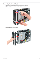
Removing the Optical Drive
1.
See “Removing the Side Panel” on page 30.
2.
See “Removing the Front Bezel” on page 31.
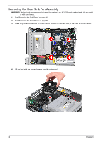
3.
See “Removing the Heat Sink Fan Assembly” on page 32.
4.
See “Removing the Processor” on page 34.
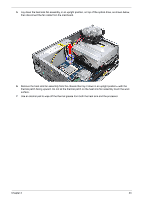
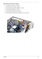
5.
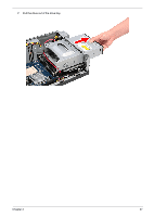
Disconnect the data and power cables from the rear of the optical drive and the mainboard.
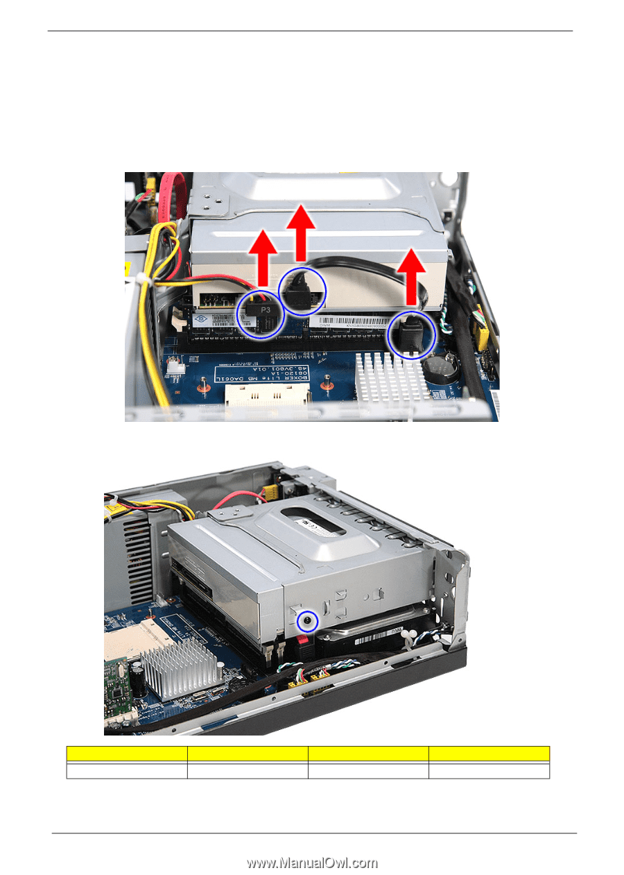
6.
Remove the screw (B) from the optical drive.
Screw (Quantity)
Color
Torque
Part No.
M3xL5 (1)
Black
5.5 to 6.5 kgf-cm
86.1A324.5R0