Acer EL1210 Service Guide - Page 60
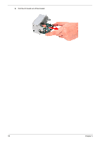
Remove the six screws C that secure the mainboard to the chassis, in the order shown.
 |
View all Acer EL1210 manuals
Add to My Manuals
Save this manual to your list of manuals |
Page 60 highlights
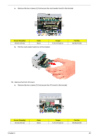
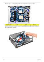
11. Remove the six screws (C) that secure the mainboard to the chassis, in the order shown. Screw (Quantity) #6-32 L5 BZN (6) Color Silver 12. Lift the board from the chassis. Torque 5.5 to 6.5 kgf-cm Part No. 86.00J44.C60 52 Chapter 3
-
 1
1 -
2
-
3
-
4
-
5
-
6
-
7
-
8
-
9
-
10
-
11
-
12
-
13
-
14
-
15
-
16
-
17
-
18
-
19
-
20
-
21
-
22
-
23
-
24
-
25
-
26
-
27
-
28
-
29
-
30
-
31
-
32
-
33
-
34
-
35
-
36
-
37
-
38
-
39
-
40
-
41
-
42
-
43
-
44
-
45
-
46
-
47
-
48
-
49
-
50
-
51
-
52
-
53
-
54
-
 55
55 -
 56
56 -
 57
57 -
 58
58 -
 59
59 -
 60
60 -
 61
61 -
 62
62 -
 63
63 -
 64
64 -
 65
65 -
66
-
67
-
68
-
69
-
70
-
71
-
72
-
73
-
74
-
75
-
76
-
77
-
78
-
79
-
80
-
81
-
82
-
83
-
84
-
85
-
86
 |
 |

52
Chapter 3
11.
Remove the six screws (C) that secure the mainboard to the chassis, in the order shown.
12.
Lift the board from the chassis.
Screw (Quantity)
Color
Torque
Part No.
#6-32 L5 BZN (6)
Silver
5.5 to 6.5 kgf-cm
86.00J44.C60