Acer EL1210 Service Guide - Page 55
Removing the Front I/O and Card Reader Boards
 |
View all Acer EL1210 manuals
Add to My Manuals
Save this manual to your list of manuals |
Page 55 highlights
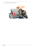
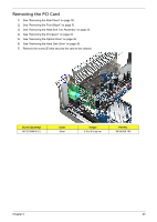
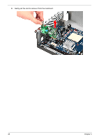
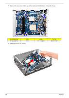
Removing the Front I/O and Card Reader Boards 1. See "Removing the Side Panel" on page 30. 2. See "Removing the Front Bezel" on page 31. 3. See "Removing the Heat Sink Fan Assembly" on page 32. 4. See "Removing the Processor" on page 34. 5. See "Removing the Optical Drive" on page 36. 6. See "Removing the Hard Disk Drive" on page 38. 7. See "Removing the Memory Modules" on page 44. 8. Disconnect one end of the USB and audio cables from the front I/O and card reader boards. 9. Open the cable retention clip, then disconnect the USB and audio cables from the mainboard. 10. Remove the front I/O and card reader board bracket. Chapter 3 47
-
 1
1 -
2
-
3
-
4
-
5
-
6
-
7
-
8
-
9
-
10
-
11
-
12
-
13
-
14
-
15
-
16
-
17
-
18
-
19
-
20
-
21
-
22
-
23
-
24
-
25
-
26
-
27
-
28
-
29
-
30
-
31
-
32
-
33
-
34
-
35
-
36
-
37
-
38
-
39
-
40
-
41
-
42
-
43
-
44
-
45
-
46
-
47
-
48
-
49
-
 50
50 -
 51
51 -
 52
52 -
 53
53 -
 54
54 -
 55
55 -
 56
56 -
 57
57 -
 58
58 -
 59
59 -
 60
60 -
61
-
62
-
63
-
64
-
65
-
66
-
67
-
68
-
69
-
70
-
71
-
72
-
73
-
74
-
75
-
76
-
77
-
78
-
79
-
80
-
81
-
82
-
83
-
84
-
85
-
86
 |
 |

Chapter 3
47
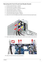
Removing the Front I/O and Card Reader Boards
1.
See “Removing the Side Panel” on page 30.
2.
See “Removing the Front Bezel” on page 31.
3.
See “Removing the Heat Sink Fan Assembly” on page 32.
4.
See “Removing the Processor” on page 34.
5.
See “Removing the Optical Drive” on page 36.
6.
See “Removing the Hard Disk Drive” on page 38.
7.
See “Removing the Memory Modules” on page 44.
8.
Disconnect one end of the USB and audio cables from the front I/O and card reader boards.
9.
Open the cable retention clip, then disconnect the USB and audio cables from the mainboard.
10.
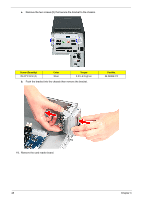
Remove the front I/O and card reader board bracket.