Asus M4A88TD-V EVO/USB3 User Manual - Page 54
M4A88TD-V EVO/USB3 System panel connector - flash drive
 |
View all Asus M4A88TD-V EVO/USB3 manuals
Add to My Manuals
Save this manual to your list of manuals |
Page 54 highlights
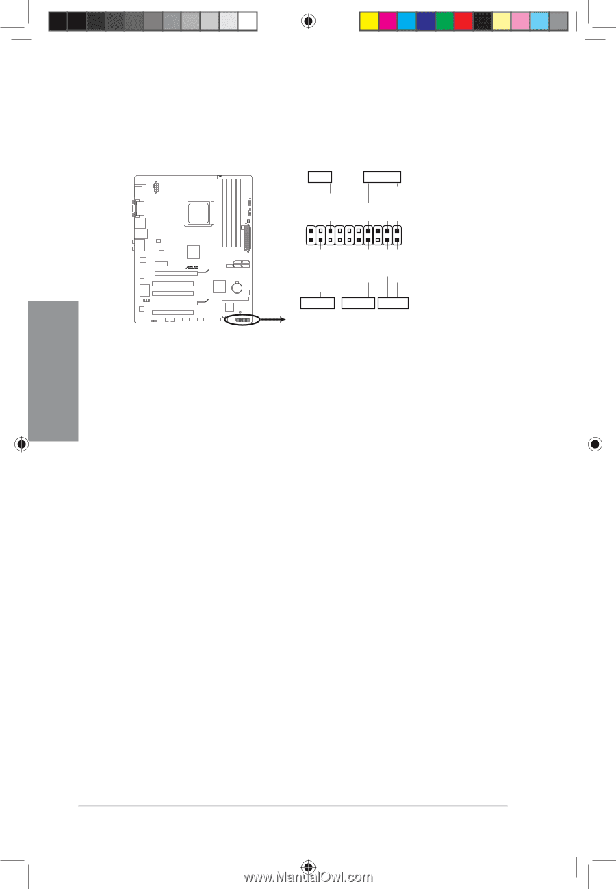
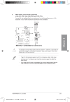
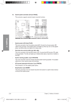
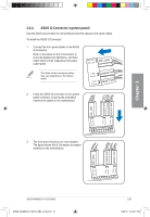
Chapter 2 10. System panel connector (20-8 pin PANEL) This connector supports several chassis-mounted functions. PLED SPEAKER PLED+ PLED+5V Ground Ground Speaker IDE_LED+ IDE_LED- PWR Ground Reset Ground PANEL PIN 1 M4A88TD-V EVO/USB3 IDE_LED PWRSW RESET * Requires an ATX power supply M4A88TD-V EVO/USB3 System panel connector • System power LED (2-pin PLED) This 2-pin connector is for the system power LED. Connect the chassis power LED cable to this connector. The system power LED lights up when you turn on the system power, and blinks when the system is in sleep mode. • Hard disk drive activity LED (2-pin IDE_LED) This 2-pin connector is for the HDD Activity LED. Connect the HDD Activity LED cable to this connector. The IDE LED lights up or flashes when data is read from or written to the HDD. • System warning speaker (4-pin SPEAKER) This 4-pin connector is for the chassis-mounted system warning speaker. The speaker allows you to hear system beeps and warnings. • ATX power button/soft-off button (2-pin PWRSW) This connector is for the system power button. • Reset button (2-pin RESET) This 2-pin connector is for the chassis-mounted reset button for system reboot without turning off the system power. 2-36 E5888_M4A88TD-V EVO-USB3_Content36 36 Chapter 2: Hardware information 5/26/10 3:45:06 PM
-
 1
1 -
2
-
3
-
4
-
5
-
6
-
7
-
8
-
9
-
10
-
11
-
12
-
13
-
14
-
15
-
16
-
17
-
18
-
19
-
20
-
21
-
22
-
23
-
24
-
25
-
26
-
27
-
28
-
29
-
30
-
31
-
32
-
33
-
34
-
35
-
36
-
37
-
38
-
39
-
40
-
41
-
42
-
43
-
44
-
45
-
46
-
47
-
48
-
 49
49 -
 50
50 -
 51
51 -
 52
52 -
 53
53 -
 54
54 -
 55
55 -
 56
56 -
 57
57 -
 58
58 -
 59
59 -
60
-
61
-
62
-
63
-
64
-
65
-
66
-
67
-
68
-
69
-
70
-
71
-
72
-
73
-
74
-
75
-
76
-
77
-
78
-
79
-
80
-
81
-
82
-
83
-
84
-
85
-
86
-
87
-
88
-
89
-
90
-
91
-
92
-
93
-
94
-
95
-
96
-
97
-
98
-
99
-
100
-
101
-
102
-
103
-
104
-
105
-
106
-
107
-
108
-
109
-
110
-
111
-
112
-
113
-
114
-
115
-
116
-
117
-
118
-
119
-
120
-
121
-
122
-
123
-
124
-
125
-
126
-
127
-
128
 |
 |