Asus M4A88TD-V EVO/USB3 User Manual - Page 55
ASUS Q-Connector system panel
 |
View all Asus M4A88TD-V EVO/USB3 manuals
Add to My Manuals
Save this manual to your list of manuals |
Page 55 highlights
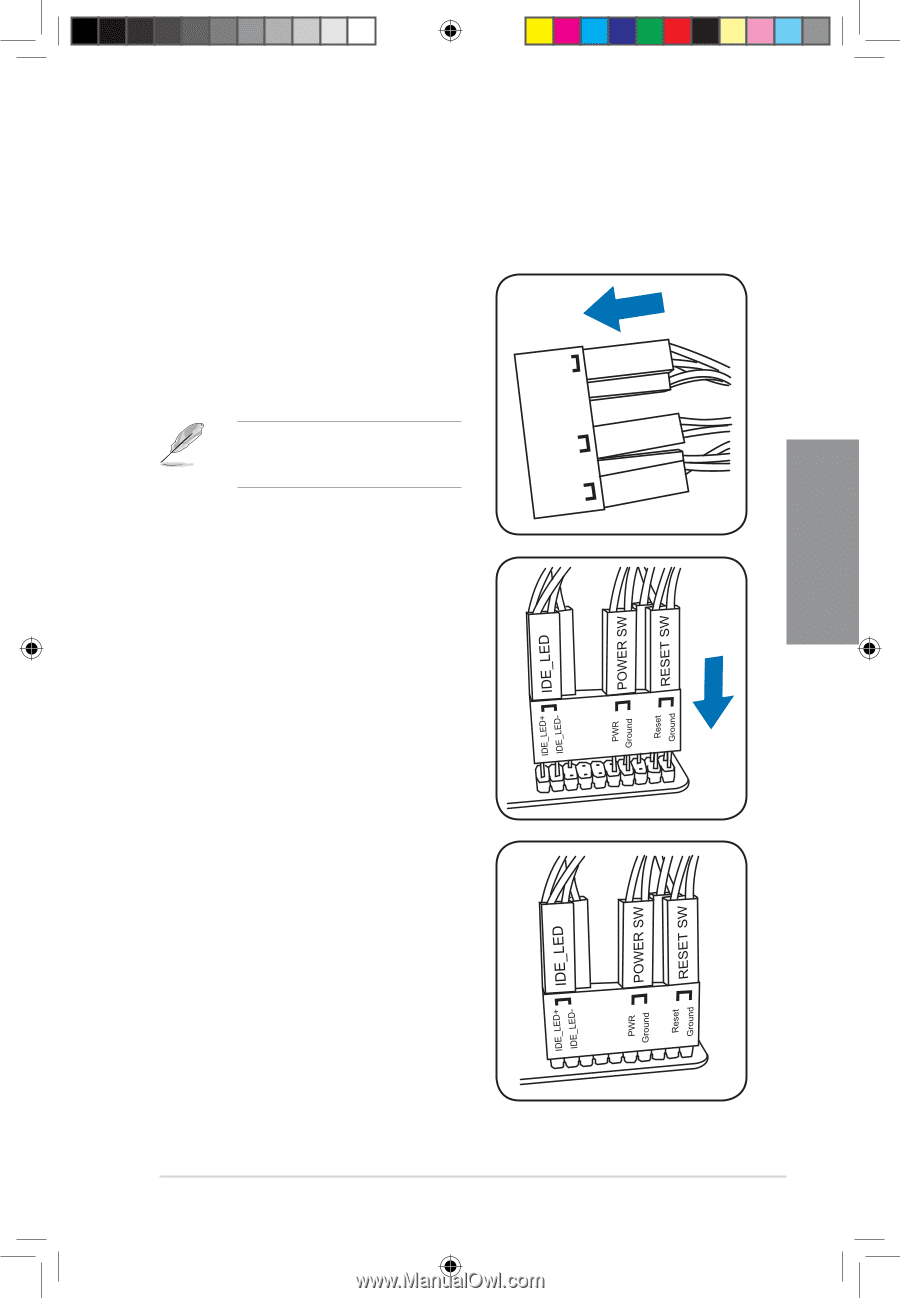
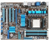
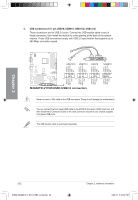
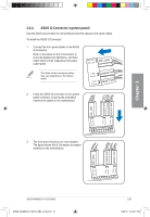
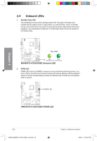
Chapter 2 2.8.4. ASUS Q-Connector (system panel) Use the ASUS Q-Connector to connect/disconnect the chassis front panel cables. To install the ASUS Q-Connector: 1. Connect the front panel cables to the ASUS Q-Connector. Refer to the labels on the Q-Connector to know the detailed pin definitions, and then match them to their respective front panel cable labels. IDE_LED+ IDE_LED- IDE_LED The labels on the front panel cables may vary depending on the chassis model. PWR Ground Reset Ground POWER SW RESET SW 2. Install the ASUS Q-Connector to the system panel connector, ensuring the orientation matches the labels on the motherboard. 3. The front panel functions are now enabled. The figure shows the Q-Connector is properly installed on the motherboard. ASUS M4A88TD-V EVO/USB3 E5888_M4A88TD-V EVO-USB3_Content37 37 2-37 5/26/10 3:45:07 PM
-
 1
1 -
2
-
3
-
4
-
5
-
6
-
7
-
8
-
9
-
10
-
11
-
12
-
13
-
14
-
15
-
16
-
17
-
18
-
19
-
20
-
21
-
22
-
23
-
24
-
25
-
26
-
27
-
28
-
29
-
30
-
31
-
32
-
33
-
34
-
35
-
36
-
37
-
38
-
39
-
40
-
41
-
42
-
43
-
44
-
45
-
46
-
47
-
48
-
49
-
 50
50 -
 51
51 -
 52
52 -
 53
53 -
 54
54 -
 55
55 -
 56
56 -
 57
57 -
 58
58 -
 59
59 -
 60
60 -
61
-
62
-
63
-
64
-
65
-
66
-
67
-
68
-
69
-
70
-
71
-
72
-
73
-
74
-
75
-
76
-
77
-
78
-
79
-
80
-
81
-
82
-
83
-
84
-
85
-
86
-
87
-
88
-
89
-
90
-
91
-
92
-
93
-
94
-
95
-
96
-
97
-
98
-
99
-
100
-
101
-
102
-
103
-
104
-
105
-
106
-
107
-
108
-
109
-
110
-
111
-
112
-
113
-
114
-
115
-
116
-
117
-
118
-
119
-
120
-
121
-
122
-
123
-
124
-
125
-
126
-
127
-
128
 |
 |