Asus P5S-B P5S-B User Manual - Page 13
Iii. H/w Setup - drive audio
 |
View all Asus P5S-B manuals
Add to My Manuals
Save this manual to your list of manuals |
Page 13 highlights
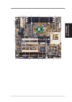
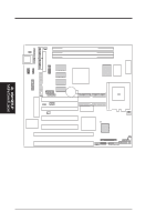
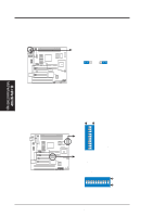
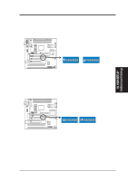
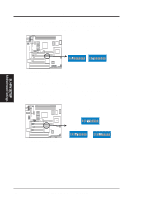
III. H/W SETUP Contents III. HARDWARE SETUP Motherboard Feature Settings 1) KB_UP p. 16 Keyboard Power (Wake) Up (Enable/Disable) 2) DIP 1 - Switch 1 p. 17 VGA Frame Buffer Setting (Shared/Local) 3) DIP 1 - Switch 2 p. 17 Onboard VGA Setting (Enable/Disable) 4) DIP 1 - Switch 3 p. 18 Onboard Audio Setting (Enable/Disable) 5) DIP 1 - Switches 4, 5 p. 18 VIO Setting 6) DIP 2 - Switch 9 p. 19 TV Out Setting (AV/RGB) 7) DIP 2 - Switch 10 p. 19 LCD Setting (Enable/Disable) 8) DIP 2 - Switches 1, 2, 3, 4 p. 20 CPU BUS Frequency Setting 9) DIP 2 - Switch 5 p. 20 Memory Transfer Mode Setting 10) DIP 2 - Switches 6, 7, 8 p. 21 CPU Core:BUS Frequnecy Multiple Setting 11) DIP 1 - Switches 6, 7, 8, 9, 10 p. 23 Voltage Regulator Output Selection Expansion Slots/Sockets 1) DIMM Sockets p. 25 168-Pin DIMM Memory Expansion Sockets 2) CPU ZIF Socket 7 3) SLOT 1, SLOT 2 p. 27 Central Processing Unit (CPU) Socket p. 29 16-bit ISA Bus Expansion Slots* 4) PCI 1, PCI2, PCI3, PCI4 p. 29 32-bit PCI Bus Expansion Slots *The onboard hardware monitor uses the address 290H-297H so legacy ISA cards must not use this address or else conflicts will occur. External Connectors 1) PS2KB 2) FLOPPY 3) PARALLEL 4) COM1/COM2 5) FAN 6) SMB 7) PRIMARY/SECOND.IDE 8) IDELED 9) ATXPWR 10) PS2PWR 11) USBMIR 12) IR 13) PWR (PANEL) 14) IDELED (PANEL) 15) PLED (PANEL) 16) RESET (PANEL) 17) MLED (PANEL) 18) KEYLOCK (PANEL) 19) SPEAKER (PANEL) 20) WOLCON p. 31 AT Keyboard Connector (5-pin Female) p. 31 Floppy Disk Drive Connector (6-pin Female) p. 32 Parallel Port Connector (26-1 pins) p. 32 Serial Port Connectors (Two 10-1 pins) p. 33 Cooling Fan Connectors (3 pins) p. 33 SMBus Connector (5-1 pins) p. 34 Primary/Secondary IDE Connector (Two 40-1 pins) p. 34 IDE Activity LED (2 pins) p. 35 ATX Power Supply Connector (20 pins) p. 35 AT Power Supply Connector (12 pins) p. 36 USB,PS/2Mouse,InfraredModuleConnector(18-1pins) p. 36 IrDA-Compliant Infrared Module Connector (5 pins) p. 37 ATX Power Switch/Soft Power Switch Lead (2 pins) p. 37 IDE Activity LED Lead (2 pins) p. 37 System Power LED Lead (2 pins) p. 37 Reset Switch Lead (2 pins) p. 37 System Message LED (2 pins) p. 37 Keyboard Lock Switch Lead (2 pins) p. 37 Speaker Output Connector (4 pins) p. 38 Wake-On-LAN Activity Connector (3 pins) ASUS P5S-B User's Manual 13
-
 1
1 -
2
-
3
-
4
-
5
-
6
-
7
-
 8
8 -
 9
9 -
 10
10 -
 11
11 -
 12
12 -
 13
13 -
 14
14 -
 15
15 -
 16
16 -
 17
17 -
 18
18 -
19
-
20
-
21
-
22
-
23
-
24
-
25
-
26
-
27
-
28
-
29
-
30
-
31
-
32
-
33
-
34
-
35
-
36
-
37
-
38
-
39
-
40
-
41
-
42
-
43
-
44
-
45
-
46
-
47
-
48
-
49
-
50
-
51
-
52
-
53
-
54
-
55
-
56
-
57
-
58
-
59
-
60
-
61
-
62
-
63
-
64
-
65
-
66
-
67
-
68
-
69
-
70
-
71
-
72
-
73
-
74
-
75
-
76
-
77
-
78
-
79
-
80
-
81
-
82
-
83
-
84
-
85
-
86
-
87
-
88
-
89
-
90
-
91
-
92
-
93
-
94
-
95
-
96
-
97
-
98
-
99
-
100
-
101
-
102
-
103
-
104
 |
 |
