Asus P5S-B P5S-B User Manual - Page 31
External Connectors - drives
 |
View all Asus P5S-B manuals
Add to My Manuals
Save this manual to your list of manuals |
Page 31 highlights
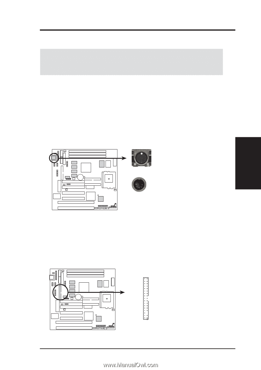
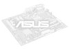
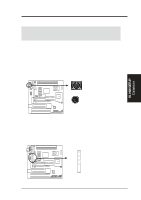
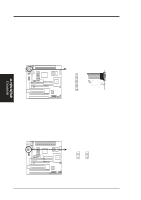
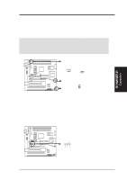
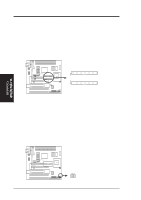
III. HARDWARE SETUP 5. External Connectors WARNING! Some pins are used for connectors or power sources. These are clearly separated from jumpers in the motherboard layout. Placing jumper caps over these will cause damage to your motherboard. IMPORTANT! Ribbon cables should always be connected with the red stripe on the Pin 1 side of the connector. The four corners of the connectors are labeled on the motherboard. Pin 1 is the side closest to the power connector on hard drives and some floppy drives. IDE ribbon cable must be less than 18in. (46cm), with the second drive connector no more than 6in. (15cm) from the first connector. 1. Keyboard Connector (5-pin Female) This connection supports either a standard IBM-compatible, 101/102-key, or 104-key keyboard (Windows 95/98-compatible). Keyboard Connector (5-pin female) This motherboard accepts an AT Keyboard Connector Plug as shown here. P5S-B Keyboard Connector 2. Floppy Disk Drive Connector (FLOPPY, 34-1 pin block ) This connector supports the provided floppy drive ribbon cable. After connecting the single end to the board, connect the two plugs on the other end to the floppy drives. (Pin 5 is removed to prevent inserting in the wrong orientation when using ribbon cables with pin 5 plugged). Floppy Disk Drive Connector III. H/W SETUP Connectors 01 01 Pin 1 P5S-B Floppy Disk Drive Connector ASUS P5S-B User's Manual 31
-
 1
1 -
2
-
3
-
4
-
5
-
6
-
7
-
8
-
9
-
10
-
11
-
12
-
13
-
14
-
15
-
16
-
17
-
18
-
19
-
20
-
21
-
22
-
23
-
24
-
25
-
 26
26 -
 27
27 -
 28
28 -
 29
29 -
 30
30 -
 31
31 -
 32
32 -
 33
33 -
 34
34 -
 35
35 -
 36
36 -
37
-
38
-
39
-
40
-
41
-
42
-
43
-
44
-
45
-
46
-
47
-
48
-
49
-
50
-
51
-
52
-
53
-
54
-
55
-
56
-
57
-
58
-
59
-
60
-
61
-
62
-
63
-
64
-
65
-
66
-
67
-
68
-
69
-
70
-
71
-
72
-
73
-
74
-
75
-
76
-
77
-
78
-
79
-
80
-
81
-
82
-
83
-
84
-
85
-
86
-
87
-
88
-
89
-
90
-
91
-
92
-
93
-
94
-
95
-
96
-
97
-
98
-
99
-
100
-
101
-
102
-
103
-
104
 |
 |