Asus P5S-B P5S-B User Manual - Page 36
USB, PS/2 Mouse, Infrared, Module Connector USBMIR, 18-1 pin block
 |
View all Asus P5S-B manuals
Add to My Manuals
Save this manual to your list of manuals |
Page 36 highlights
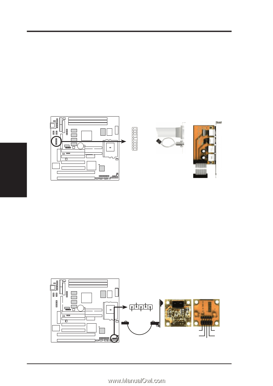
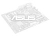
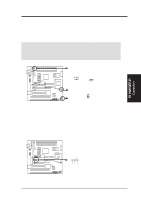
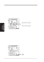
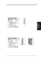
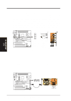
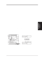
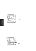
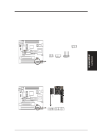
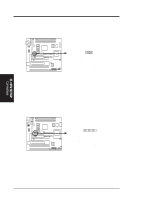
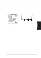
III. HARDWARE SETUP 11. USB, PS/2 Mouse, Infrared, Module Connector (USBMIR, 18-1 pin block) If you want to use PS/2 mouse, USB, or infrared (IrDA) devices, you need to purchase an optional USB/MIR connector set. You may use the bundled PS/2 mouse/parallel port connector set if you just want to use a PS/2 mouse. Either connector set connects to the 18-pin block and mounts to an open slot on your computer's chassis. The system will direct IRQ12 to the PS/2 mouse if one is detected. If not detected, expansion cards can use IRQ12. See PS/2 Mouse Control in BIOS Features Setup and USB Function in PnP and PCI Setup under BIOS SETUP. See Second IrDA... connector for details on the infrared connector. 01 9 18 Parallel Connector Infrared PS/2 Mouse 1 10 PS/2 Mouse Connector USB 0 9: +5 Volt 18: Infrared Transmit USB 1 8: (no connection) 17: Infrared Receive 7: Ground 16: Ground 6: PS/2 Mouse Clock 15: PS/2 Mouse Data 5: USB +5 Volt 14: Key 4: Ground 13: Ground 3: USB Port 0 + 12: USB Port 1 + 2: USB Port 0 - 11: USB Port 1 - 1: USB +5 Volt 10: USB +5 Volt Optional USB/MIR P5S-B PS/2 Mouse, USB, IrDA Module Connector 12. IrDA-Compliant Infrared Module Connector (IR, 5-pin block) This connector supports the optional wireless transmitting and receiving infrared module. This module mounts to a small opening on system cases that support this feature. You must also configure the setting through UART2 Use Infrared in Chipset Features Setup to select whether UART2 is directed for use with COM2 or IrDA. Use the five pins as shown below (Back View) and connect a ribbon cable from the module to the motherboard according to the pin definitions. III. H/W SETUP ConCnPeUctors 01 (NC) GND +5V IRRX IRTX P5S-B Infrared Module Connector Front View Back View IRTX GND IRRX +5V (NC) 36 ASUS P5S-B User's Manual
-
 1
1 -
2
-
3
-
4
-
5
-
6
-
7
-
8
-
9
-
10
-
11
-
12
-
13
-
14
-
15
-
16
-
17
-
18
-
19
-
20
-
21
-
22
-
23
-
24
-
25
-
26
-
27
-
28
-
29
-
30
-
 31
31 -
 32
32 -
 33
33 -
 34
34 -
 35
35 -
 36
36 -
 37
37 -
 38
38 -
 39
39 -
 40
40 -
 41
41 -
42
-
43
-
44
-
45
-
46
-
47
-
48
-
49
-
50
-
51
-
52
-
53
-
54
-
55
-
56
-
57
-
58
-
59
-
60
-
61
-
62
-
63
-
64
-
65
-
66
-
67
-
68
-
69
-
70
-
71
-
72
-
73
-
74
-
75
-
76
-
77
-
78
-
79
-
80
-
81
-
82
-
83
-
84
-
85
-
86
-
87
-
88
-
89
-
90
-
91
-
92
-
93
-
94
-
95
-
96
-
97
-
98
-
99
-
100
-
101
-
102
-
103
-
104
 |
 |