Asus P5S-B P5S-B User Manual - Page 40
ASUS P5S-B User's Manual, TV Out Connector 12-1 pin SCART, LCD Header 20-1 pin LCDHD
 |
View all Asus P5S-B manuals
Add to My Manuals
Save this manual to your list of manuals |
Page 40 highlights
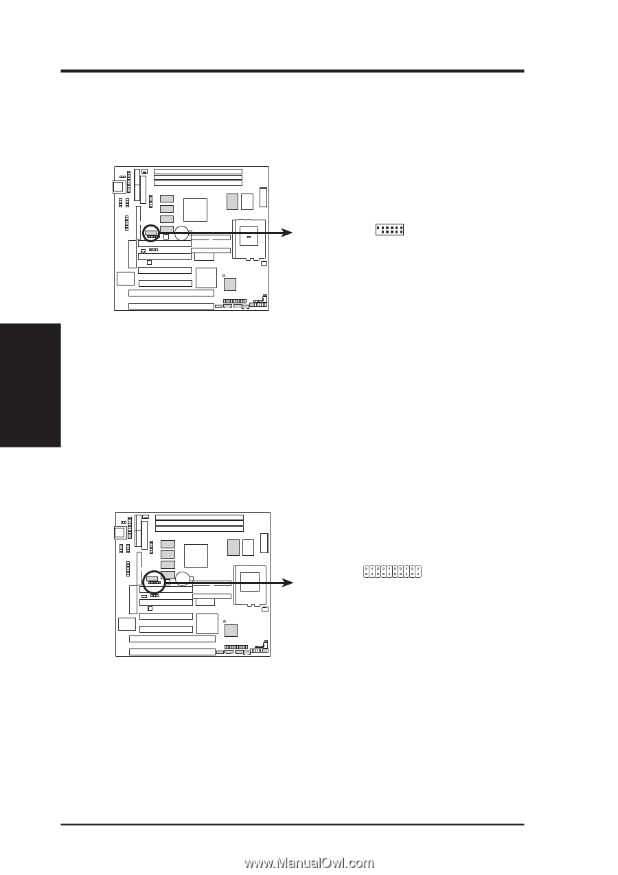
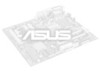
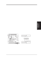
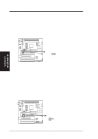
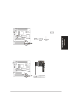
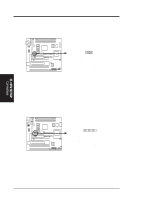
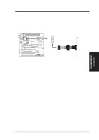
III. H/W SETUP Connectors III. HARDWARE SETUP 25. TV Out Connector (12-1 pin SCART) This connector allows you to connect your computer directly to a TV with a SCART socket. NOTE: This connector is available only on motherboards with the optional SCART interface support. 01 P5S-B TV Out Connector SCART 6 1 12 7 1: MODEM_IN 2: SYNC 3: RGB/AV# 4: GND 5: GND 6: GND 7: GND 8: GND 9: LUMA 10: CHROMA 11: COMPOSITE 12: (No Connection) 26. LCD Header (20-1 pin LCDHD) The LCD Header lets you connect an LCD monitor through the provided LCD cable with mounting bracket. Connect the cable to this header and mount the bracket to the case on a free expansion slot. You can make available the LCD port by setting DIP 2 - Switch 10 to Enable (ON). NOTE: This connector is available only on motherboards with the optional Digital Flat Panel (DFP) support. 01 P5S-B LCD Header LCDHD 11 20 1 10 1: FDDCCLK 2: PLSENSE 3: GND 4: TXC+ 5: TX06: GND 7: TX1+ 8: TX29: GND 10: (No connection) 11: FDDCDAT 12: 0+5V 13: TXC14: GND 15: TX0+ 16: TX117: GND 18: TX2+ 19: (No connection) 20: (No connection) 40 ASUS P5S-B User's Manual
-
 1
1 -
2
-
3
-
4
-
5
-
6
-
7
-
8
-
9
-
10
-
11
-
12
-
13
-
14
-
15
-
16
-
17
-
18
-
19
-
20
-
21
-
22
-
23
-
24
-
25
-
26
-
27
-
28
-
29
-
30
-
31
-
32
-
33
-
34
-
 35
35 -
 36
36 -
 37
37 -
 38
38 -
 39
39 -
 40
40 -
 41
41 -
 42
42 -
 43
43 -
 44
44 -
 45
45 -
46
-
47
-
48
-
49
-
50
-
51
-
52
-
53
-
54
-
55
-
56
-
57
-
58
-
59
-
60
-
61
-
62
-
63
-
64
-
65
-
66
-
67
-
68
-
69
-
70
-
71
-
72
-
73
-
74
-
75
-
76
-
77
-
78
-
79
-
80
-
81
-
82
-
83
-
84
-
85
-
86
-
87
-
88
-
89
-
90
-
91
-
92
-
93
-
94
-
95
-
96
-
97
-
98
-
99
-
100
-
101
-
102
-
103
-
104
 |
 |