Asus P5S-B P5S-B User Manual - Page 33
Positive, Ground, Rotation
 |
View all Asus P5S-B manuals
Add to My Manuals
Save this manual to your list of manuals |
Page 33 highlights
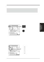
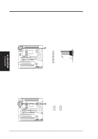
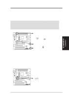
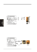
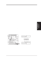
GND +12V Rotation Rotation +12V GND III. H/W SETUP Connectors III. HARDWARE SETUP 5. Cooling Fan Connectors (FAN, 3 pins) These connectors support 3-pin CPU cooling fans of 500mA (6W) or less with a minimum of 3,500RPM. Depending on the fan manufacturer, the wiring and plug may be different. The red wire should be Positive, the black should be Ground, and the yellow wire should be Rotation signal. WARNING! The CPU and/or motherboard will overheat if there is no airflow across the CPU. Damage may occur to the motherboard and/or the CPU fan if these pins are incorrectly used. These are not jumpers, do not place jumper caps over these pins. Power Supply Fan 01 P5S-B 12Volt Cooling Fan Power CPU Fan Power GND +12V Rotation Chassis Fan Power 6. SMBus Connector (5-1 pin SMB) This connector allows you to connect SMBus devices. SMBus devices communicate by means of the SMBus with an SMBus host and/or other SMBus devices. The SMBus or System Management Bus is a specific implementation of an I2C bus, which is a multi-master bus, that is, multiple chips can be connected to the same bus and each one can act as a master by initiating data transfer. 01 SMBDATA SMBCLK Ground +5V P5S-B SMBus Connector ASUS P5S-B User's Manual 33
-
 1
1 -
2
-
3
-
4
-
5
-
6
-
7
-
8
-
9
-
10
-
11
-
12
-
13
-
14
-
15
-
16
-
17
-
18
-
19
-
20
-
21
-
22
-
23
-
24
-
25
-
26
-
27
-
 28
28 -
 29
29 -
 30
30 -
 31
31 -
 32
32 -
 33
33 -
 34
34 -
 35
35 -
 36
36 -
 37
37 -
 38
38 -
39
-
40
-
41
-
42
-
43
-
44
-
45
-
46
-
47
-
48
-
49
-
50
-
51
-
52
-
53
-
54
-
55
-
56
-
57
-
58
-
59
-
60
-
61
-
62
-
63
-
64
-
65
-
66
-
67
-
68
-
69
-
70
-
71
-
72
-
73
-
74
-
75
-
76
-
77
-
78
-
79
-
80
-
81
-
82
-
83
-
84
-
85
-
86
-
87
-
88
-
89
-
90
-
91
-
92
-
93
-
94
-
95
-
96
-
97
-
98
-
99
-
100
-
101
-
102
-
103
-
104
 |
 |
