Asus P5S-B P5S-B User Manual - Page 19
ASUS P5S-B User's Manual, LCD Setting, DIP 2 - Switch 10, LCD Header, External Connectors, TV Out
 |
View all Asus P5S-B manuals
Add to My Manuals
Save this manual to your list of manuals |
Page 19 highlights
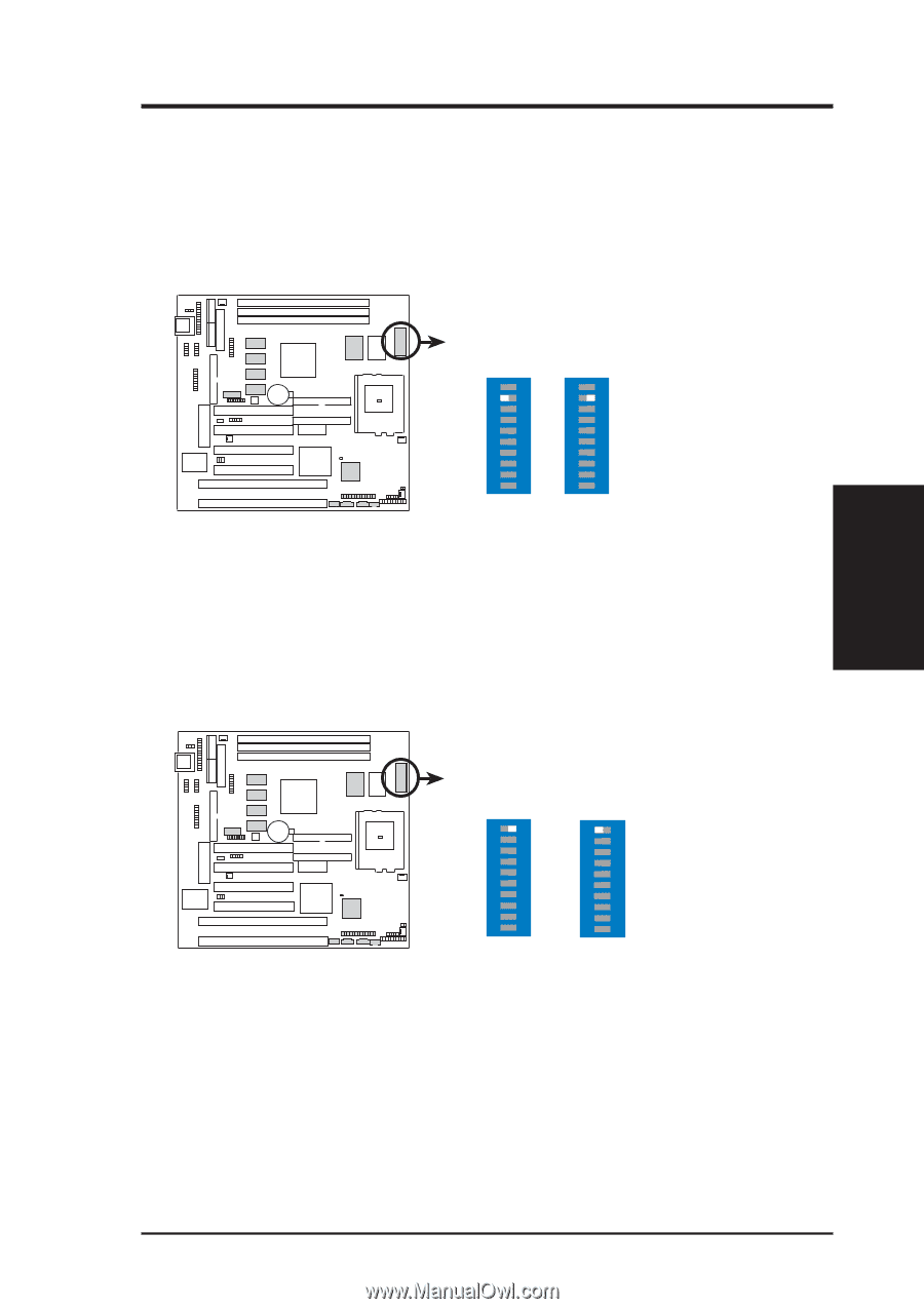
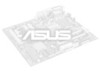
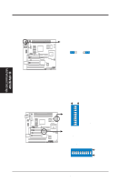
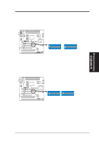
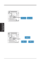
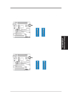
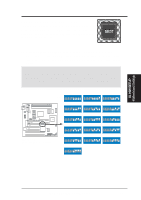
III. H/W SETUP Motherboard Settings III. HARDWARE SETUP 7. TV Out Setting (DIP 2 - Switch 9) This lets you select the signal that is inputted to your TV when using the optional TV Out connector. Select AV for a composite input or RGB for an RGB input. NOTE: This setting is available only on motherboards with the optional SCART interface support. 01 DIP 2 AV RGB ON 1 2 3 4 5 6 7 8 9 10 ON 1 2 3 4 5 6 7 8 9 10 P5S-B TV Out (SCART) Setting 6. LCD Setting (DIP 2 - Switch 10) If you want to connect an LCD monitor to your computer, you must set this switch to Enable to use it. See LCD Header in External Connectors for connection information. NOTE: This setting is available only on motherboards with the optional Digital Flat Panel (DFP) support. 01 DIP 2 Disable (Default) Enable ON 1 2 3 4 5 6 7 8 9 10 ON 1 2 3 4 5 6 7 8 9 10 P5S-B LCD Setting ASUS P5S-B User's Manual 19
-
 1
1 -
2
-
3
-
4
-
5
-
6
-
7
-
8
-
9
-
10
-
11
-
12
-
13
-
 14
14 -
 15
15 -
 16
16 -
 17
17 -
 18
18 -
 19
19 -
 20
20 -
 21
21 -
 22
22 -
 23
23 -
 24
24 -
25
-
26
-
27
-
28
-
29
-
30
-
31
-
32
-
33
-
34
-
35
-
36
-
37
-
38
-
39
-
40
-
41
-
42
-
43
-
44
-
45
-
46
-
47
-
48
-
49
-
50
-
51
-
52
-
53
-
54
-
55
-
56
-
57
-
58
-
59
-
60
-
61
-
62
-
63
-
64
-
65
-
66
-
67
-
68
-
69
-
70
-
71
-
72
-
73
-
74
-
75
-
76
-
77
-
78
-
79
-
80
-
81
-
82
-
83
-
84
-
85
-
86
-
87
-
88
-
89
-
90
-
91
-
92
-
93
-
94
-
95
-
96
-
97
-
98
-
99
-
100
-
101
-
102
-
103
-
104
 |
 |