Asus P5S-B P5S-B User Manual - Page 39
Stereo Audio In Connector 4-pin AUX, CD1, CD2
 |
View all Asus P5S-B manuals
Add to My Manuals
Save this manual to your list of manuals |
Page 39 highlights
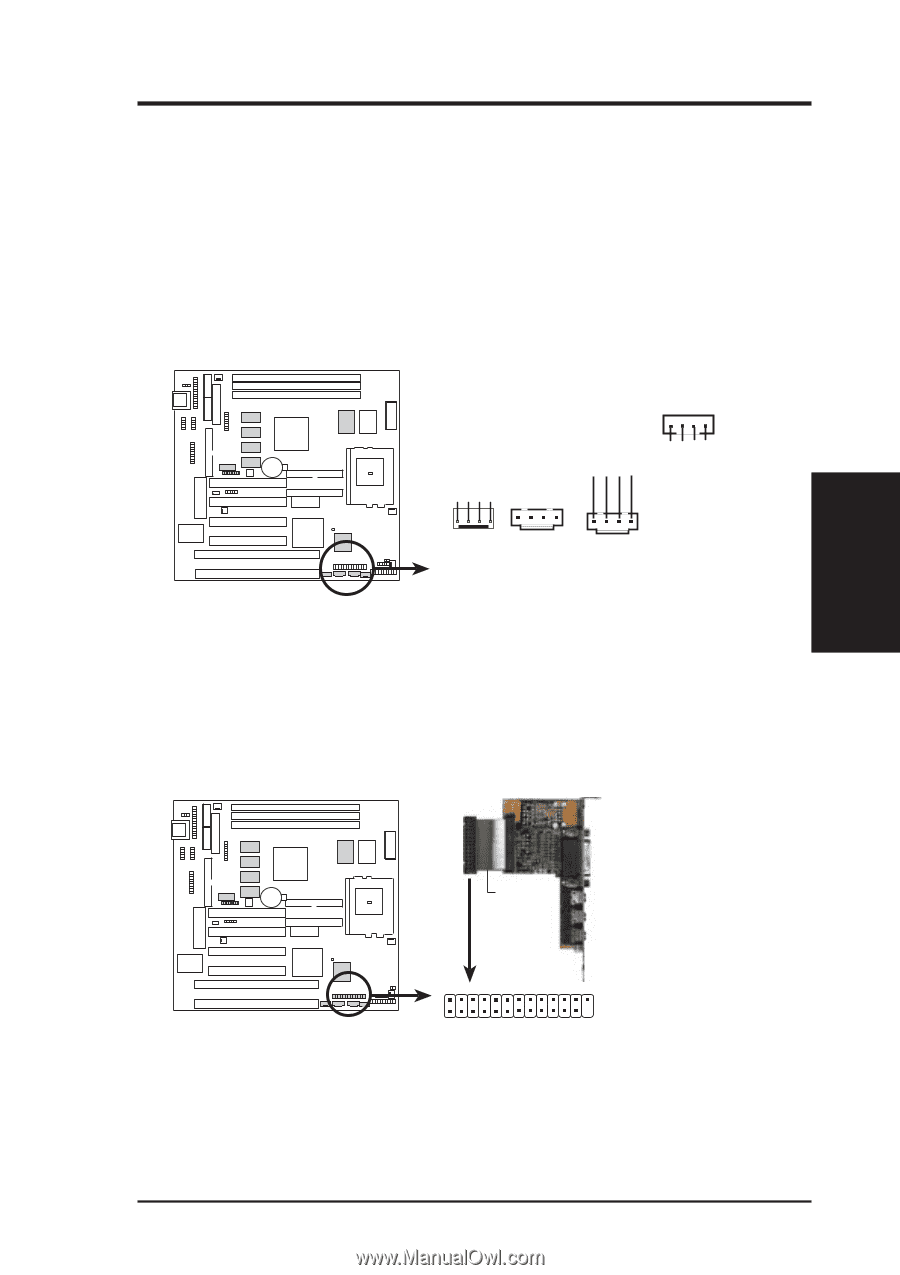
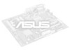
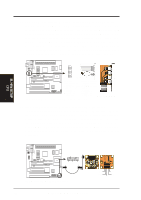
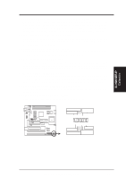
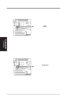
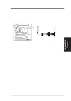
Modem-In Ground Ground Modem-Out Left Audio Channel Ground Ground Right Audio Channel Right Audio Channel Ground Left Audio Channel Ground III. H/W SETUP Connectors III. HARDWARE SETUP 22. Stereo Audio In Connector (4-pin AUX, CD1, CD2) / 23. Voice Modem In Connector (4-pin MODEM) AUX, CD1 and CD2 allow you to receive stereo audio input from an internal CD-ROM drive or other sound sources, such as the ASUS TV Box, TV tuner or MPEG card. MODEM allows the optional onboard audio to interface with a voice modem card. It also allows the sharing of microphone and speaker between the onboard audio and the voice modem card. To use this feature, your voice modem card must have a similar connector. NOTE: This connector is available only on motherboards with the optional onboard audio support. CD2 01 MODEM AUX CD1 NOTE: AUX is the same as CD1 P5S-B Internal Audio Connectors 24. Audio Header (26-1 pin AUDIOCON) This header supports the optional connector set for sudio input/output and game/ MIDI port. This connector set connects to the 25-pin block and mounts to an open slot on your computer's chassis. NOTE: This connector is available only on motherboards with the optional onboard audio support. 01 21 Red stripe Audio Connector Module Game/MIDI Port (15 pins) Line Output (1/8" phono) Microphone In (1/8" phono) Line Input (1/8" phono) 2 26 1 25 P5S-B Audio Header ASUS P5S-B User's Manual 39
-
 1
1 -
2
-
3
-
4
-
5
-
6
-
7
-
8
-
9
-
10
-
11
-
12
-
13
-
14
-
15
-
16
-
17
-
18
-
19
-
20
-
21
-
22
-
23
-
24
-
25
-
26
-
27
-
28
-
29
-
30
-
31
-
32
-
33
-
 34
34 -
 35
35 -
 36
36 -
 37
37 -
 38
38 -
 39
39 -
 40
40 -
 41
41 -
 42
42 -
 43
43 -
 44
44 -
45
-
46
-
47
-
48
-
49
-
50
-
51
-
52
-
53
-
54
-
55
-
56
-
57
-
58
-
59
-
60
-
61
-
62
-
63
-
64
-
65
-
66
-
67
-
68
-
69
-
70
-
71
-
72
-
73
-
74
-
75
-
76
-
77
-
78
-
79
-
80
-
81
-
82
-
83
-
84
-
85
-
86
-
87
-
88
-
89
-
90
-
91
-
92
-
93
-
94
-
95
-
96
-
97
-
98
-
99
-
100
-
101
-
102
-
103
-
104
 |
 |