Bose Lifestyle 48 Installation guide - Page 14
English - inputs
 |
View all Bose Lifestyle 48 manuals
Add to My Manuals
Save this manual to your list of manuals |
Page 14 highlights
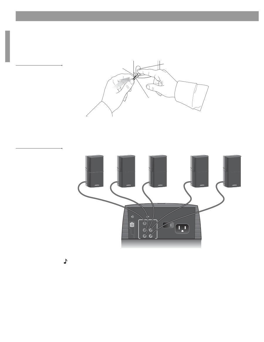
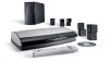
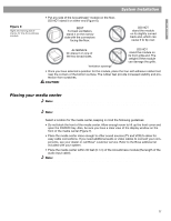
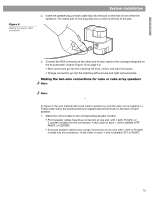
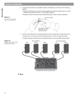
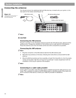
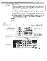
English System Installation Figure 9 Connecting the two-wire cable to cube speakers 2. Connect the wire end of one speaker cable to the terminals on the rear of the matching speaker. • Press the terminal tab on the back of the speaker and insert the marked wire (+) into the red terminal and the plain wire (-) into the black terminal. • Release the tab to secure the wire. Repeat this step for each of the five speakers. Terminal tab Left, Right, or Center printed on the red collar on (+) wire Figure 10 Speaker connections to the Acoustimass module 3. Connect each cable to the corresponding jack on the Acoustimass® module (Figure 10). • Plug the blue connectors into the matching left front, center, and right front jacks. • Plug the orange connectors into the matching left surround and right surround jacks. Front speakers Left Center Right Surround speakers Left Right FRONT L FRONT C FRONT R SURROUND L SURROUND R AUDIO INPUT OUTPUTS TO CUBE SPEAKERS FRONT SURROUND L C L R R POWER 100-120/200-240VAC 50/60 Hz 350W MAX. Acoustimass module connector panel Note: You may find it more convenient to place the Acoustimass module upside down while making connections. When done, place it on any of its sides but not on either end or top. 14
-
 1
1 -
2
-
3
-
4
-
5
-
6
-
7
-
8
-
 9
9 -
 10
10 -
 11
11 -
 12
12 -
 13
13 -
 14
14 -
 15
15 -
 16
16 -
 17
17 -
 18
18 -
 19
19 -
20
-
21
-
22
-
23
-
24
-
25
-
26
-
27
-
28
-
29
-
30
-
31
-
32
-
33
-
34
-
35
-
36
 |
 |