Bose Lifestyle 48 Installation guide - Page 27
Reference - media center
 |
View all Bose Lifestyle 48 manuals
Add to My Manuals
Save this manual to your list of manuals |
Page 27 highlights
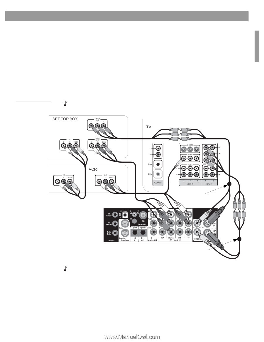
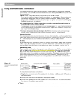
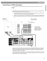
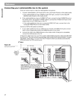
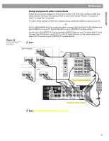
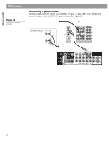
English Figure 23 Component video connection Reference Using Component video connections Follow the connection diagram in Figure 23 to achieve the best video quality for DVD and cable/satellite viewing, while adding a VCR to your home theater. Refer to "Component video" on page 24, if necessary. To watch DVDs and see LIFESTYLE® system menus, select the VIDEO 4 input on your TV, or, if your cable/satellite box has component jacks, connect them as shown in the diagram and select VIDEO 4 on your TV. Select CBL/SAT on your LIFESTYLE® system remote. Connect the VCR (VIDEO OUT) to an available VIDEO IN jack on your TV. Select that TV input. Connect the VCR (Audio L and R OUT) to the TV Audio IN jacks on the media center and select the TV source on your LIFESTYLE® system remote. Note: To make the connections shown in the diagram below, you will need additional cables. Component video adapter Component video adapter Note: Two comonent video adapters are provided. 27
-
 1
1 -
2
-
3
-
4
-
5
-
6
-
7
-
8
-
9
-
10
-
11
-
12
-
13
-
14
-
15
-
16
-
17
-
18
-
19
-
20
-
21
-
 22
22 -
 23
23 -
 24
24 -
 25
25 -
 26
26 -
 27
27 -
 28
28 -
 29
29 -
 30
30 -
 31
31 -
 32
32 -
33
-
34
-
35
-
36
 |
 |