Bose Lifestyle 48 Installation guide - Page 19
Connecting the system to power - acoustimass
 |
View all Bose Lifestyle 48 manuals
Add to My Manuals
Save this manual to your list of manuals |
Page 19 highlights
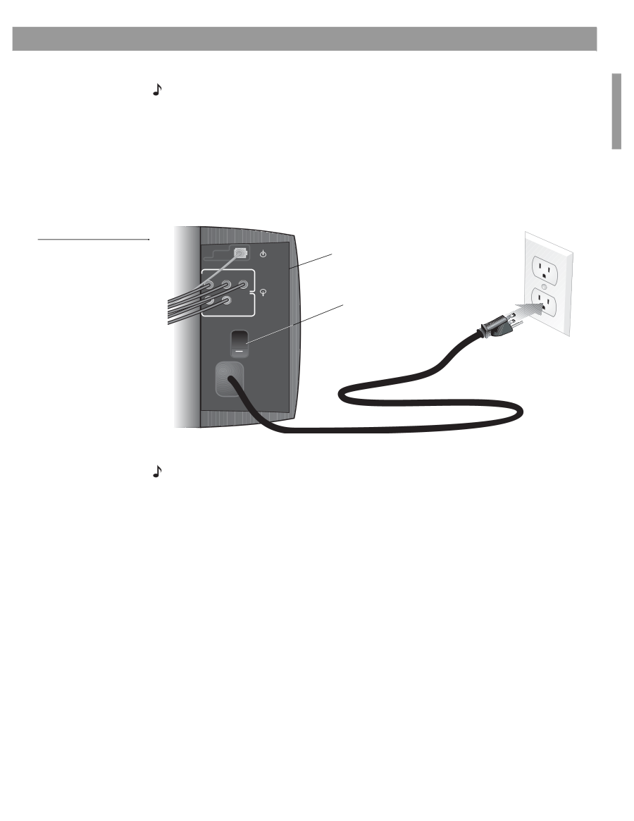
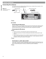
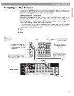
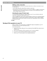
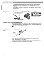
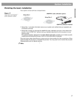
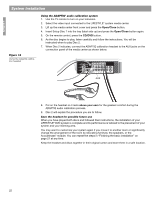
English System Installation Connecting the system to power Note: Bose recommends using a quality surge suppressor on all electronics equipment. Voltage variations and spikes can damage electronic components in any system. A quality suppressor can eliminate the vast majority of failures attributed to surges and may be purchased at electronics stores. Connect the two AC power (mains) cords in the following order: 1. Plug the small end of the Acoustimass® module power cord into the AC power jack on the connector panel of the Acoustimass module (Figure 14). 2. Plug the other end of the power cord into an AC (mains) outlet. 3. Turn the Acoustimass module POWER switch to on. Figure 14 Power connection for the Acoustimass module AUDIO INPUT Acoustimass module connector panel L C R OUTPUTSTO CUBE SPEAKERS FRONT SURROUND Power switch | = ON O = OFF L R POWER 100-120/200-240VAC 50/60 Hz 350W MAX. Note: For dual voltage units (sold in certain areas), make sure the voltage setting on the bottom of the media center power supply matches the local power rating (Figure 15). Check with local electrical authorities if you are not sure of the appropriate power rating. 19
-
 1
1 -
2
-
3
-
4
-
5
-
6
-
7
-
8
-
9
-
10
-
11
-
12
-
13
-
 14
14 -
 15
15 -
 16
16 -
 17
17 -
 18
18 -
 19
19 -
 20
20 -
 21
21 -
 22
22 -
 23
23 -
 24
24 -
25
-
26
-
27
-
28
-
29
-
30
-
31
-
32
-
33
-
34
-
35
-
36
 |
 |