Brother International BAS-342G Thread Break Detector Instruction Manual - Engl - Page 9
Negro; No. 12: Azul
 |
View all Brother International BAS-342G manuals
Add to My Manuals
Save this manual to your list of manuals |
Page 9 highlights
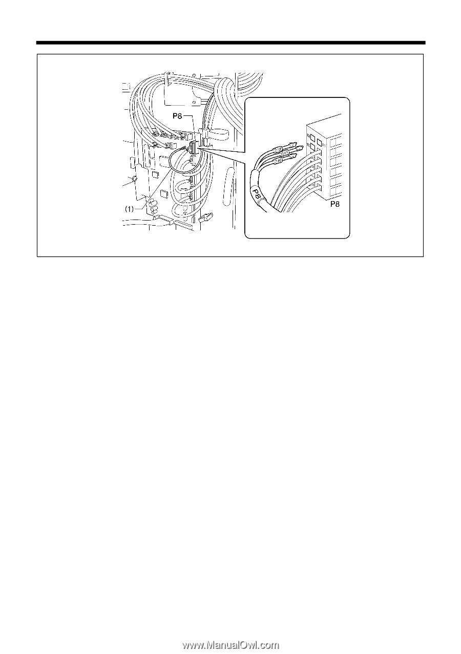
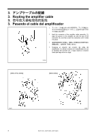
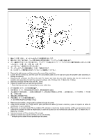
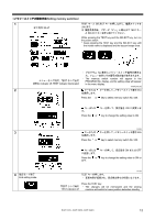
5267Q 2 8 3. 締ねじ(4)[2 5 1 4 P8 1 10 11 12 5 P8 6 8 2. Remove the eight screws, and then remove the cover of the control box. 3. Loosen the two screws (4), and then open the cord presser plate (5) to the right and pass the amplifier cable assembly (1) through the opening. 4. Disconnect the connector from P8 on the main P.C. board, and insert the pins while checking that the wire marks on the amplifier cable assembly (1) match the connector numbers. (No. 10: Brown; No. 11: Black; No. 12: Blue) 5. Insert the connector into P8 on the main P.C. board. 6. Tighten the control box cover with the eight screws. * Check that the cords are not clamped by the cover at this time. 2 8 3 4)[2 5 1)通过。 4 P8 1 10 11 号为黑 色、12 5 P8 处。 6 8 2. Retire los ocho tornillos, y luego quite la cubierta de la caja de control. 3. Afloje los dos tornillos (4), y luego abra la placa prensora de cables (5) hacia la derecha y pase el conjunto de cable de amplificador (1) por la abertura. 4. Desconecte el conector desde P8 en el tablero P.C. principal, e inserte las clavijas mientras verifica que las marcas de los cables en el conjunto de cable de amplificador (1) estén de acuerdo con los números de conectores. (No. 10: Marrón; No. 11: Negro; No. 12: Azul) 5. Inserte el conector en P8 en el tablero P.C. principal. 6. Apriete la cubierta de la caja de controles con los ocho tornillos. * Verifique que los cables no son apretados por la cubierta. BAS-311G, BAS-326G, BAS-342G 8
-
 1
1 -
2
-
3
-
 4
4 -
 5
5 -
 6
6 -
 7
7 -
 8
8 -
 9
9 -
 10
10 -
 11
11 -
 12
12 -
 13
13 -
 14
14 -
15
-
16
-
17
-
18
-
19
-
20
 |
 |