Brother International CB3-B917 Service Manual - Page 13
Thread trimmer mechanism
 |
View all Brother International CB3-B917 manuals
Add to My Manuals
Save this manual to your list of manuals |
Page 13 highlights
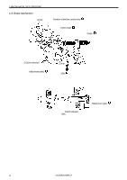
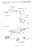
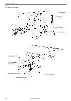
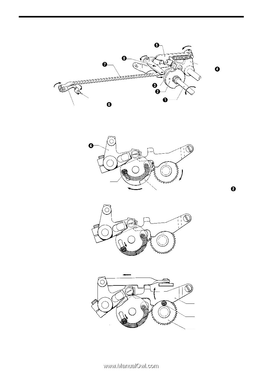
1. MECHANICAL DESCRIPTIONS 1-7. Thread trimmer mechanism Connecting rod 4 Connecting lever Thread cutter connecting rod 2 6 5 7 Pawl Number of stitches adjustment cam Fixed knife Movable knife Cam shaft 123s 3 Thread trimming lever 1. Rotation Thread trimming lever Number of stitches adjustment lever Number of stitches 6, 8 124s Number of stitches adjustment cam Number of stitches 12, 16 125s Number of stitches 24, 32 126s Stitch 32 lever Roller Number of stitches adjustment gear 7 CB3-B916A/B917A
-
 1
1 -
2
-
3
-
4
-
5
-
6
-
7
-
 8
8 -
 9
9 -
 10
10 -
 11
11 -
 12
12 -
 13
13 -
 14
14 -
 15
15 -
 16
16 -
 17
17 -
 18
18 -
19
-
20
-
21
-
22
-
23
-
24
-
25
-
26
-
27
-
28
-
29
-
30
-
31
-
32
-
33
-
34
-
35
-
36
-
37
-
38
-
39
-
40
-
41
-
42
-
43
-
44
-
45
-
46
-
47
-
48
-
49
-
50
-
51
-
52
-
53
-
54
-
55
-
56
 |
 |
1. MECHANICAL DESCRIPTIONS
CB3-B916A/B917A
7
1-7. Thread trimmer mechanism
124s
125s
126s
Number of stitches 6, 8
Number of stitches 12, 16
Number of stitches 24, 32
Thread trimming lever
Number of stitches adjustment lever
Number of stitches adjustment cam
Number of stitches
adjustment gear
Stitch 32 lever
Roller
123s
1. Rotation
Cam shaft
Number of stitches adjustment cam
Pawl
Thread trimming
lever
Connecting rod
Connecting lever
Thread cutter connecting rod
Movable knife
7
2
3
4
6
5
Fixed knife