Brother International CB3-B917 Service Manual - Page 22
the uppermost reference line A with the bottom of
 |
View all Brother International CB3-B917 manuals
Add to My Manuals
Save this manual to your list of manuals |
Page 22 highlights
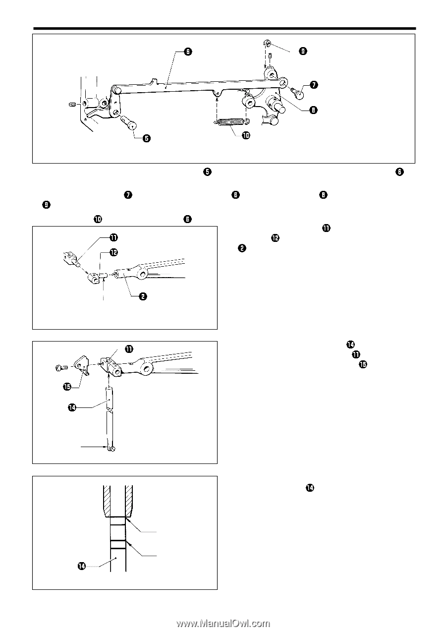
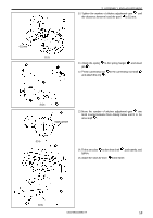
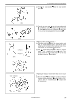
3. ASSEMBLY AND ADJUSTMENT 304s 5. With the screw flat of the thread take-up lever shaft facing toward you, pass it through the tension release rod , insert into the frame, push lightly, and tighten the screw. 6. Pass the adjustment shaft through the tension release rod and presser driving lever , and then fit the snap ring and tighten with a screw. 7. Attach the spring to the tension release rod and the frame pin. 8. Fit the needle bar clamp to the needle bar clamp connector , and then fit to the needle bar drive lever . Apply grease 305s 9. With the cut part of the needle bar facing toward you, pass it through the needle bar clamp , and then tighten together with the needle thread take-up . Cut part 306s 307s A (TQx1) B (TQx7) < Adjustment of the needle bar height > Move the needle bar to the lowest position and align the uppermost reference line A with the bottom of the needle bar metal. * For a TQx7 needle, use the second reference line B from the bottom. CB3-B916A/B917A 16
-
 1
1 -
2
-
3
-
4
-
5
-
6
-
7
-
8
-
9
-
10
-
11
-
12
-
13
-
14
-
15
-
16
-
 17
17 -
 18
18 -
 19
19 -
 20
20 -
 21
21 -
 22
22 -
 23
23 -
 24
24 -
 25
25 -
 26
26 -
 27
27 -
28
-
29
-
30
-
31
-
32
-
33
-
34
-
35
-
36
-
37
-
38
-
39
-
40
-
41
-
42
-
43
-
44
-
45
-
46
-
47
-
48
-
49
-
50
-
51
-
52
-
53
-
54
-
55
-
56
 |
 |